Hook-face polisher

A polishing machine and curved surface technology, applied in the field of polishing machines, can solve the problems of low usage rate of processing consumables, poor consistency of the entire plate workpiece, low yield rate of workpieces, etc., and achieve the effects of improving yield rate, uniform loss, and improving utilization rate

Inactive Publication Date: 2017-05-10
YUHUAN CNC MACHINE TOOL
View PDF6 Cites 11 Cited by
  • Summary
  • Abstract
  • Description
  • Claims
  • Application Information

AI Technical Summary

Problems solved by technology

It will lead to the disadvantages of low polishing yield rate of curved surface, low polishing efficiency, and low utilization rate of processing consumables.
At the same time, the lower workpiece plate only has self-rotation movement, no revolution, and there are disadvantages such as inconsistent wear of processing consumables, poor consistency of the entire plate, and low yield of workpieces.
[0003] With the increasing demand for complex curved surface polishing in the field of electron optics, traditional polishing equipment is difficult to match the rapidly developing processing requirements due to defects such as low processing efficiency, low usage rate of processing consumables, and low yield of workpieces.

Method used


Image

  • Hook-face polisher

Examples


Embodiment Construction

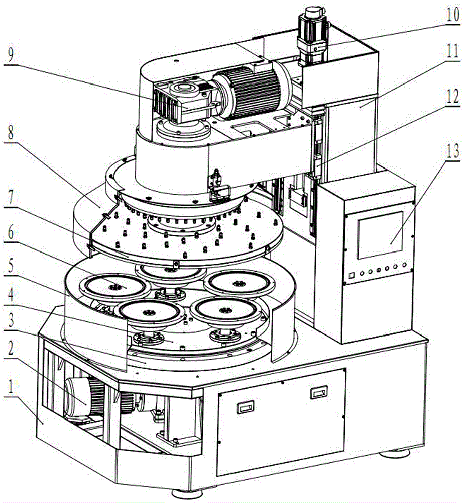
[0012] Such as figure 1 As shown, the curved surface polishing equipment of the present invention includes a bed 1, a lower plate power system 2, a slewing bearing support assembly 3, a revolution plate 4, a liquid receiving basin 5, a workpiece plate assembly 6, an upper plate assembly 7, a liquid shield 8, Various functional modules such as the upper plate power system 9, the servo feed system 10, the column component 11, the linear slider assembly 12, and the numerical control system 13. The bed 1 is provided with a bottom plate power system 2, and the bottom plate power system 2 mainly provides the revolution movement of the workpiece plate; the bed 1 is provided with a slewing bearing support assembly 3 connected with the bottom plate power system 2, The revolving disk 4 is supported by the slewing bearing support assembly 3, and the revolving disk 4 is evenly provided with five workpiece disk assemblies 6 that are connected to the lower plate power system 2 and can rotat...


PUM


Abstract

The invention discloses a hook-face polisher. The hook-face polisher comprises a lower power system which is arranged on a bed body, a pivotal bearing support component connected with the lower power system, a public turnplate supported by the pivotal bearing support component, multiple self-rotational workpiece disk components which are connected with the lower power system and are arranged on the public turnplate, an upper disk component which is arranged above the workpiece disk components and is installed on a stand column assembly, and an upper power system which is arranged on the upper disk component and is used for driving upper disks in the upper disk component to rotate, a servo feed system which is arranged on the stand column assembly and is used for driving the upper disk component to move up and down along the stand column, and a numerical control system which is arranged on the bed body. According to hook-face polisher, the spin motion and the revolution motion of the lower workpiece disk can be achieved, the loss of processed consumable items (hairbrushes) can be more uniform, and the yield of a workpiece is increased; the purpose that an upper polishing disk can conduct real-time compensation orientation along with the loss of the processed consumable items can be achieved through a servo driving system, thus the consistency of hook face polishing in the whole processing procedure is guaranteed, and the usage rate and the processing efficiency of the processed consumable items are increased.

Description

technical field [0001] The invention belongs to polishing machines, in particular to a curved surface polishing machine. Background technique [0002] At present, in the field of traditional curved surface polishing, a cylinder is usually used to control the up and down movement of the upper polishing disc and realize pressurization. When working, a limit ring is used to limit the upper polishing disc at a fixed point. The limit ring bears the main pressure of the upper plate, and the surface of the workpiece only bears the pressure generated by the deformation of the processing consumables. It will lead to the disadvantages of low polishing yield rate of curved surface, low polishing efficiency, and low utilization rate of processing consumables. At the same time, the lower workpiece plate only has self-rotation motion and no revolution, so there are disadvantages such as inconsistent wear of processing consumables, poor consistency of workpieces on the entire plate, and ...

Claims


Application Information

Patent Timeline
Patent Type & Authority Applications(China)
IPC IPC(8): B24B29/00B24B29/02B24B55/04B24B57/00B24B47/12B24B47/00B24B27/00
CPCB24B29/005B24B27/0069B24B29/02B24B47/00B24B47/12B24B55/04B24B57/00
Inventor 许亮唐湘平尹荆州罗铁
Owner YUHUAN CNC MACHINE TOOL
Why Eureka
Try Eureka