
Temperature control device of pseudo artificial joint part abrasive flow turbulence polishing equipment temperature control device and method thereof

A technology of artificial joints and temperature control devices, which can be applied to used abrasive processing devices, metal processing equipment, and electric temperature control, etc. It can solve the problems of poor uniformity of processing effects, achieve uniform processing quality, and improve the effect , the effect of high polishing precision

Active Publication Date: 2017-05-10
ZHEJIANG UNIV OF TECH
View PDF6 Cites 0 Cited by
  • Summary
  • Abstract
  • Description
  • Claims
  • Application Information

AI Technical Summary

Problems solved by technology

[0007] The purpose of the present invention is to solve the problem that the turbulent total kinetic energy of the abrasive particle flow changes with time in the process of the turbulent precision machining of the existing artificial joint parts, which leads to the poor uniformity of the machining effect in the entire machining process, and provides a kind of artificial joint. Temperature control device and method for abrasive particle flow turbulent flow polishing equipment for joint parts

Method used


Image

  • Temperature control device of pseudo artificial joint part abrasive flow turbulence polishing equipment temperature control device and method thereof
  • Temperature control device of pseudo artificial joint part abrasive flow turbulence polishing equipment temperature control device and method thereof
  • Temperature control device of pseudo artificial joint part abrasive flow turbulence polishing equipment temperature control device and method thereof

Examples


Embodiment Construction

[0025] The present invention will be further described below in conjunction with accompanying drawing:

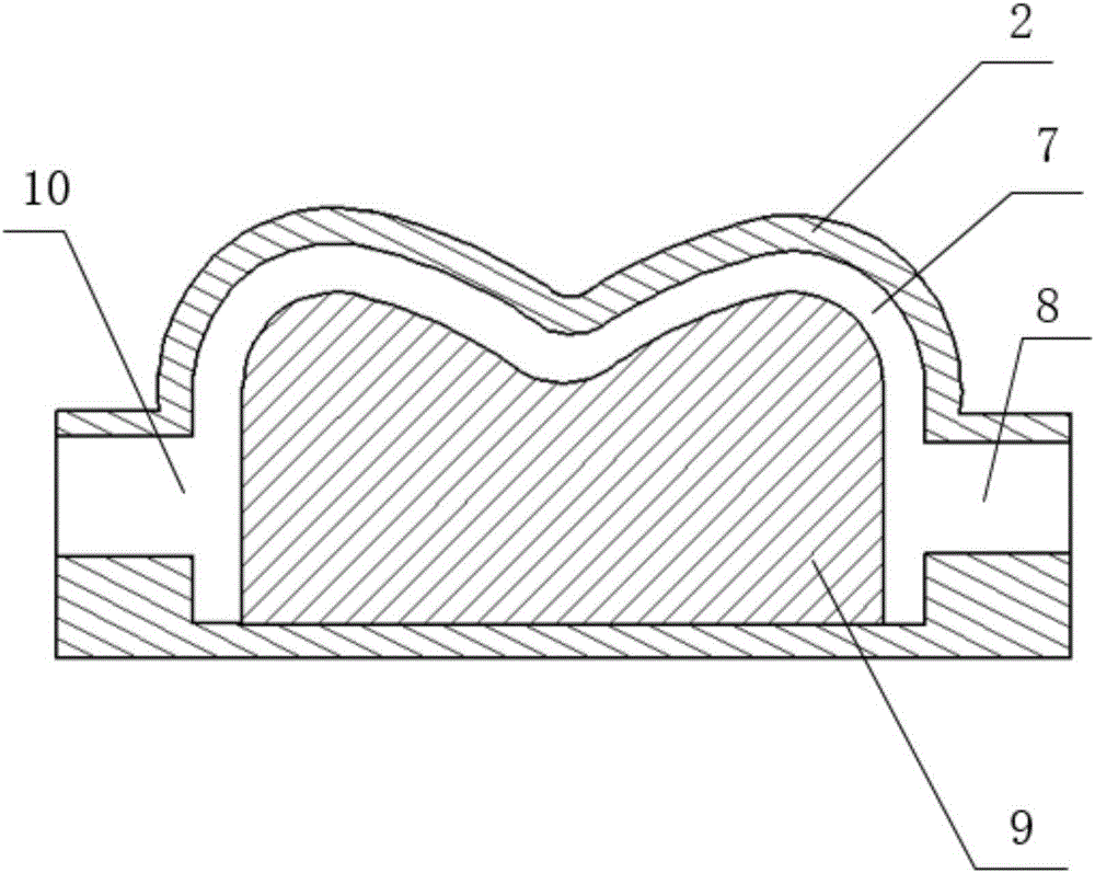
[0026] Such as Figure 1~4As shown, the temperature control device of the artificial joint-like abrasive particle flow turbulent flow polishing equipment includes a glass restraint member 4, a temperature detection device, a three-degree-of-freedom moving device 2, an electromagnetic wave heater 3, a support frame, an air film pump 5, and a stirrer 6. With the electromagnetic wave controller 1, the glass constraining member 4 is set outside the artificial joint 9, and the inner surface of the glass constraining member 4 and the curved surface of the artificial joint 9 form a profiling flow channel 7 with uniform thickness , the glass constraining member 4 is made of glass material with the same wall thickness, and the two ends of the glass constraining member 4 are respectively provided with a profiling flow channel inlet 10 and a profiling flow channel outlet 8; the profil...


PUM


Abstract

The invention discloses a temperature control device of pseudo artificial joint part abrasive flow turbulence polishing equipment temperature control device and a method thereof. The temperature control device comprises a glass constraint component, a temperature detection device, a three-freedom-degree moving device, an electromagnetic wave heater, a support frame, a gas membrane pump, a stirring device and an electromagnetic wave controller; the inner surface of the glass constraint component and the curve surface of the pseudo artificial joint part form a profiling flow passage with the uniform thickness; the profiling flow passage, the gas membrane pump and the stirrer form an abrasive flow circulation system through a pipeline; the temperature detection device is right aligned with the profiling flow passage; the three-freedom-degree moving device drives the electromagnetic wave heater to freely move in the three-dimensional space above the glass constraint component. Through the electromagnetic wave heater capable of moving along the three-freedom degree moving device which is arranged on the glass constraint component and is used for heating any position in the profiling flow passage; the turbulence kinetic energy and the speed of the abrasive flow cutting fluid in the corresponding heating position are respectively increased and accelerated, so that the integral processing effect is improved; the surface processing quality of the pseudo artificial joint part is more uniform.

Description

technical field [0001] The present invention relates to the technical field of abrasive particle flow polishing, and more specifically, relates to a temperature control device and a method thereof for artificial joint-like abrasive particle flow turbulent flow polishing equipment. Background technique [0002] Artificial joint is an artificial organ designed by people to save joints that have lost their function. It has the best curative effect among artificial organs. The commonly used materials for artificial joints are metal alloys. Among them, special titanium alloys are suitable for the manufacture of artificial joints because of their biocompatibility, corrosion resistance, and elastic modulus, which are close to those of human bones. The surface quality of artificial joints determines the surface friction properties. The greater the roughness, the higher the contact probability of asperities on the surface, resulting in increased adhesive wear. As we all know, titani...

Claims


Application Information

Patent Timeline
Patent Type & Authority Applications(China)
IPC IPC(8): B24C1/08B24C3/32B24C9/00G05D23/19
CPCB24C1/08B24C3/32B24C9/00G05D23/19
Inventor 张利袁智敏王金顺朴钟宇戴勇
Owner ZHEJIANG UNIV OF TECH
Learn More