Subsea pipeline in-situ overhaul bin

A subsea pipeline and in-situ technology, applied in the direction of pipes, pipes/pipe joints/fittings, underwater operation equipment, etc., can solve the problems of secondary damage to the network, large economic losses, low operating efficiency, etc., and achieve strong carrying capacity, The effect of a high degree of automation and a large depth of work

Active Publication Date: 2017-05-10
CHINA SHIP SCIENTIFIC RESEARCH CENTER (THE 702 INSTITUTE OF CHINA SHIPBUILDING INDUSTRY CORPORATION)
View PDF7 Cites 8 Cited by
  • Summary
  • Abstract
  • Description
  • Claims
  • Application Information

AI Technical Summary

Problems solved by technology

The traditional surface optical cable maintenance operation ship needs to pull the submarine pipeline directly to the surface ship, or salvage it to the surface ship after being cut by an underwater robot, which is inefficient and easy to cause secondary damage to the network
The maintenance of oil and gas pipelines is mostly assisted by robots in underwater wet mode after the shutdown, which results in low maintenance efficiency and large economic losses
Recently, my country has developed an underwater dry cabin, which is inflated to create a high-pressure dry environment, and personnel wear diving suits to maintain in situ in the cabin. However, due to the limitation of human physiological pressure resistance, the maximum working water depth of this method is only 60 meters

Method used


Image

  • Subsea pipeline in-situ overhaul bin
  • Subsea pipeline in-situ overhaul bin
  • Subsea pipeline in-situ overhaul bin

Examples


Embodiment Construction

[0035] Specific embodiments of the present invention will be described below.

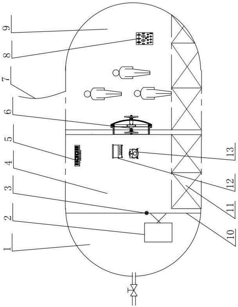
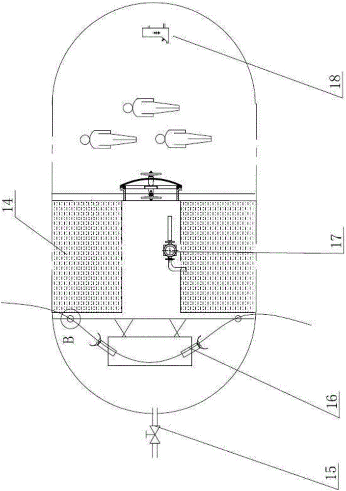
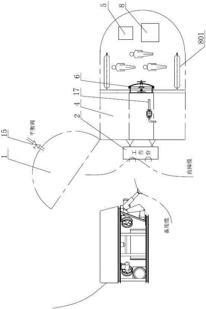
[0036] Such as figure 1 , figure 2 and image 3 As shown, a submarine pipeline in-situ maintenance cabin is composed of a dry and wet cabin 4 and a manned cabin 9 to form a pressure-resistant shell. One side of the dry and wet cabin 4 and the manned cabin 9 are provided for communicating with the dry and wet cabin. 4 and the opening and closing door 6 of the manned cabin 9, an automatic opening and closing hatch cover 1 is also arranged on the other side of the dry and wet cabin 4, which is located inside the automatic opening and closing hatch cover 1, and the above-mentioned automatic opening and closing hatch cover 1 is The channel of communication between the dry and wet cabin 4 and the seawater outside the cabin can provide the working space for the underwater robot that can assist the operation, and provide the feasibility for the pipeline to enter the cabin. An electric control system 18...


PUM


Abstract

The invention relates to a subsea pipeline in-situ overhaul bin. A pressing resistant shell is formed by fixedly connecting a dry-wet bin and a manned bin. An opening-closing door used for communicating with the dry-wet bin and the manned bin is arranged between one side of the dry-wet bin and the manned bin. An automatic opening-closing bin opening cover is further arranged on the other side of the dry-wet bin. A cable grabbing manipulator and a workbench are located in the automatic opening-closing bin opening cover. An electric control system used for providing electric power and a life support system are arranged in the manned bin. A replacement water tank, a replacement water pump, overhaul equipment, an underwater hydraulic pump, a valve box, a workbench and a cable grabbing manipulator are arranged in the dry-wet bin. The subsea pipeline in-situ overhaul bin adopts single-shell structure design, thus the space utilization rate of the subsea pipeline in-situ overhaul bin is high, the whole bin size is reduced under the same compression strength requirements, the carrying capacity is high, and the working depth is large. Balance of the underwater posture in the dry-wet bin is achieved through a water replacement principle, and the advantages of high bottom resting stability and wide usage performance are achieved. Through the arrangement of a pipeline seal structure, partial sealing of a submarine cable is achieved, and the submarine cable can enter the subsea pipeline in-situ overhaul bin and can be taken out of the subsea pipeline in-situ overhaul bin after an overhaul conveniently.

Description

technical field [0001] The invention relates to the field of marine engineering, in particular to an in-situ maintenance cabin for submarine pipelines. Background technique [0002] On the seabed near the coast of my country, there are power supply and communication networks used for oil and gas production in my country, power communication networks between offshore islands, and transoceanic submarine communication optical networks. Because they are often threatened by anchoring of shipping and fishing vessels, it is generally necessary to bury Within the depth of 0.5m-3m on the seabed. The traditional surface optical cable maintenance operation ship needs to pull the submarine pipeline directly to the surface ship, or salvage it to the surface ship after cutting by an underwater robot, which is inefficient and easy to cause secondary damage to the network. The maintenance of oil and gas pipelines is mostly assisted by robots in underwater wet mode after shutdown, which resu...

Claims


Application Information

Patent Timeline
Patent Type & Authority Applications(China)
IPC IPC(8): B63B3/13B63G8/22F16L5/10
CPCB63B3/13B63G8/22F16L5/10
Inventor 焦慧锋彭棠李霄霄赵春城付薇倪天王静张琳丹吴雨
Owner CHINA SHIP SCIENTIFIC RESEARCH CENTER (THE 702 INSTITUTE OF CHINA SHIPBUILDING INDUSTRY CORPORATION)
Why Eureka
Try Eureka