Flange of automobile engine exhausting system and production process of flange

A technology of automobile engine and exhaust system, which is applied in the direction of engine components, machines/engines, exhaust devices, etc., and can solve the problems of three-way catalytic converter carrier sintering, engine overheating, tempering, and flange size inconsistency, etc. Achieve the effect of being suitable for popularization, increasing service life and convenient installation

Inactive Publication Date: 2017-05-10
江苏多为机械工业有限公司
View PDF4 Cites 1 Cited by
  • Summary
  • Abstract
  • Description
  • Claims
  • Application Information

AI Technical Summary

Problems solved by technology

[0002] Automobile exhaust system refers to the system that collects and emits exhaust gas. It is generally composed of exhaust manifold, exhaust pipe, catalytic converter, exhaust temperature sensor, automobile muffler and exhaust tailpipe. Oil system, ignition system and other faults, engine overheating, tempering, resulting in three-way catalytic converter carrier sin

Method used


Image

  • Flange of automobile engine exhausting system and production process of flange
  • Flange of automobile engine exhausting system and production process of flange
  • Flange of automobile engine exhausting system and production process of flange

Examples


Embodiment 1

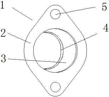
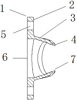
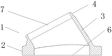
[0034] The present invention provides such as figure 1 The one shown includes a flange body 1, a bottom plate 2, a connector 3, a top plate 4, a hole 5, a bottom hole 6, and a top hole 7. The flange body 1 is provided with a bottom plate 2, and the center of the bottom plate 2 is provided with a Bottom hole 6, two holes 5 are respectively arranged on both sides of the bottom hole 6, the upper end of the bottom plate 2 is connected with the lower end of the connector 3, the upper end of the connector 3 is connected with the top plate 4, and the center of the top plate 4 is provided with a top hole 7;

[0035] The surface of the bracket body is coated with a layer of wear-resistant metal coating 12, and the components of the wear-resistant metal coating are: C: 0.21%, Mg: 0.13%, Cu: 0.62%, W: 0.45%, Ti: 0.55% , Cr: 5.32%, Ni: 0.37%, Mo: 0.42%, Co: 0.23%, Ca: 3.42%, rare earth: 11%, the rest is Fe and trace impurities;

[0036] Among the rare earths, the following components ar...

Embodiment 2

[0049] The present invention provides such as figure 1 The shown flange of an automobile engine exhaust system includes a flange body 1, a bottom plate 2, a connector 3, a top plate 4, a hole 5, a bottom hole 6 and a top hole 7, and the flange body 1 is provided with a bottom plate 2 , the center of the bottom plate 2 is provided with a bottom hole 6, and the two sides of the bottom hole 6 are respectively provided with two holes 5, the upper end of the bottom plate 2 is connected with the lower end of the connector 3, the upper end of the connector 3 is connected with the top plate 4, and the top plate The center of 4 is provided with a top hole 7;

[0050] The surface of the bracket body 1 is coated with a layer of wear-resistant metal coating 12. The components of the wear-resistant metal coating are: C: 0.23%, Mg: 0.17%, Cu: 0.65%, W: 0.48%, Ti: 0.58 %, Cr: 5.35%, Ni: 0.39%, Mo: 0.45%, Co: 0.25%, Ca: 3.45%, rare earth: 13%, the rest is Fe and trace impurities;

[0051] A...

Embodiment 3

[0064] The present invention provides such as figure 1 The shown flange of an automobile engine exhaust system includes a flange body 1, a bottom plate 2, a connector 3, a top plate 4, a hole 5, a bottom hole 6 and a top hole 7, and the flange body 1 is provided with a bottom plate 2 , the center of the bottom plate 2 is provided with a bottom hole 6, and the two sides of the bottom hole 6 are respectively provided with two holes 5, the upper end of the bottom plate 2 is connected with the lower end of the connector 3, the upper end of the connector 3 is connected with the top plate 4, and the top plate The center of 4 is provided with a top hole 7;

[0065] The surface of the bracket body 1 is coated with a layer of wear-resistant metal coating 12. The components of the wear-resistant metal coating are: C: 0.22%, Mg: 0.15%, Cu: 0.63%, W: 0.47%, Ti: 0.56 %, Cr: 5.34%, Ni: 0.38%, Mo: 0.43%, Co: 0.24%, Ca: 3.43%, rare earth: 12%, the rest is Fe and trace impurities;

[0066] A...


PUM


Abstract

The invention provides a flange of an automobile engine exhausting system. The flange comprises a flange body, a bottom plate, a connecting part, a top plate, holes, a bottom-end hole and a top hole, wherein the flange body is provided with the bottom plate; the bottom-end hole is formed in the center of the bottom plate and two holes are formed in each of two sides of the bottom-end hole; the upper end of the bottom plate is connected with the lower end of the connecting part; the upper end of the connecting part is connected with the top plate; the top hole is formed in the center of the top plate; a wear-resisting metal coating is plated on the surface of the flange body; the wear-resisting metal coating is prepared from the following components in percentage by mass: 0.21 percent to 0.23 percent of C, 0.13 percent to 0.17 percent of Mg, 0.62 percent to 0.65 percent of Cu, 0.45 percent to 0.48 percent of W, 0.55 percent to 0.58 percent of Ti, 5.32 percent to 5.35 percent of Cr, 0.37 percent to 0.39 percent of Ni, 0.42 percent to 0.45 percent of Mo, 0.23 percent to 0.25 percent of Co, 3.42 percent to 3.45 percent of Ca, 11 percent to 13 percent of rare earth and the balance of Fe and trace impurities; the rare earth includes the following components in percentage by weight: 5.2 percent to 5.5 percent of La, 7.6 percent to 7.8 percent of Ce, 5.2 percent to 5.6 percent of Pm, 5.5 percent to 5.8 percent of Nd, 3.1 percent to 3.3 percent of Eu, 5.5 percent to 5.8 percent of Sm and the balance of Gd.

Description

technical field [0001] The invention relates to the technical field of automobile engines, in particular to a flange of an automobile engine exhaust system and a production process thereof. Background technique [0002] Automobile exhaust system refers to the system that collects and emits exhaust gas. It is generally composed of exhaust manifold, exhaust pipe, catalytic converter, exhaust temperature sensor, automobile muffler and exhaust tailpipe. Oil system, ignition system and other faults, engine overheating, tempering, resulting in three-way catalytic converter carrier sintering, peeling off, exhaust resistance increases, therefore, the exhaust system flange needs to bear a certain pressure, the existing automobile engine law The flange is manufactured by assembly or stamping process, which saves the production cost, but the stability is poor, and the size of the flange is not uniform, which is not convenient for the replacement of parts. Contents of the invention ...

Claims


Application Information

Patent Timeline
IPC IPC(8): C22C38/16C22C38/12C22C38/14C22C38/18C22C38/08C22C38/10F01N13/18F01N13/16
CPCC22C38/16C22C38/002C22C38/005C22C38/08C22C38/10C22C38/12C22C38/14C22C38/18F01N13/16F01N13/18F01N13/1861F01N2510/08
Inventor 高军朱铭陈杰单剑鹏
Owner 江苏多为机械工业有限公司
Why Eureka
Try Eureka