A self-feeding dust explosion engine

A dust explosion and engine technology, applied in the directions of powdered engine fuel, combustion engine, engine components, etc., can solve the problems of complex device structure, and achieve the effect of simplifying the mechanical structure, good sealing effect, and stable performance.

Active Publication Date: 2020-05-26
ANHUI UNIVERSITY OF TECHNOLOGY
View PDF1 Cites 0 Cited by
  • Summary
  • Abstract
  • Description
  • Claims
  • Application Information

AI Technical Summary

Problems solved by technology

[0008] The purpose of the present invention is to overcome the disadvantages in the prior art that the device structure is complicate...

Method used


Image

  • A self-feeding dust explosion engine
  • A self-feeding dust explosion engine
  • A self-feeding dust explosion engine

Examples


Embodiment 1

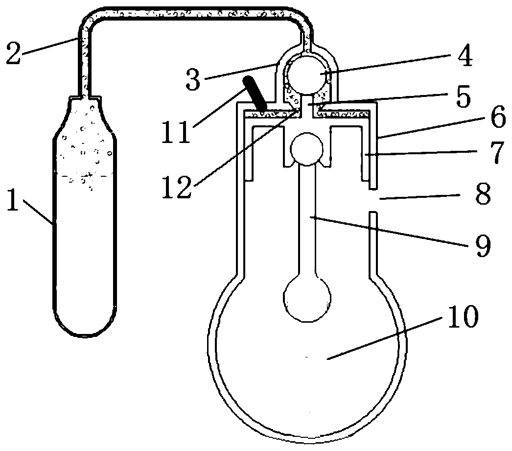
[0036] combine figure 1 , a self-feeding dust explosion engine of the present embodiment is mainly composed of a fuel tank 1, a feed chamber 3 and a piston 7, wherein: the fuel tank 1 is fed into the combustion chamber 6 through the feeding device 2; in the present embodiment The combustion chamber 6 includes a combustion chamber part and a compressed gas part, which is structurally equivalent to a cylinder block, and the feeding device 2 is used to deliver dust fuel to the combustion chamber of the combustion chamber 6 . The dust fuel can be metal dust, coal dust, grain dust, feed dust or forest product dust, etc., without specific limitation, and grain dust can be selected in this embodiment.

[0037] In this embodiment, one end of the feed chamber 3 is communicated with the feeding device 2, and the other end is communicated with the combustion chamber 6 through the feed port 12. The cavity of the feed chamber 3 is provided with a retaining ball 4, which can be placed in th...

Embodiment 2

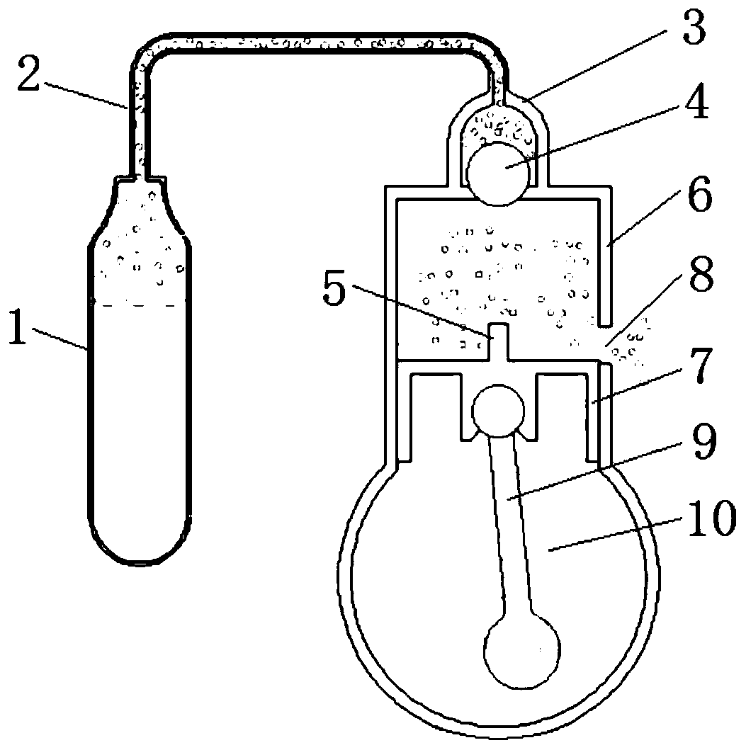
[0043] A kind of self-feeding dust explosion engine of this embodiment, its basic structure is identical with embodiment 1, and its difference is: in the present embodiment, the upper part of feeding chamber 3 is a spherical crown, namely feeding chamber 3 and feeding The connecting part of the device 2 is a spherical crown, and the diameter of the spherical crown is larger than the diameter of the retaining ball 4, so the retaining ball 4 can better cooperate with the feeding chamber 3, and the sealing is tight, which can effectively avoid the phenomenon of material leakage.

[0044] Further, the feed inlet 12 is a spherical crown opening located at the top of the combustion chamber 6, that is, the lower part of the feed chamber 3 is also a spherical crown, and the diameter of the spherical crown is larger than the diameter of the retaining ball 4. Since the diameters of both are greater than the diameter of the retaining ball, the retaining ball can completely fit closely wit...

Embodiment 3

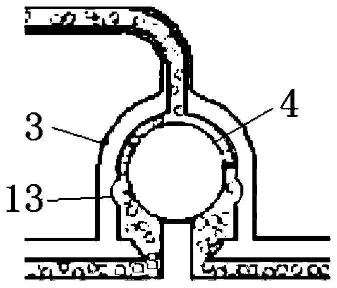
[0046] combine image 3 , a kind of self-feeding dust explosion engine of this embodiment, its basic structure is identical with embodiment 2, and its difference lies in: this embodiment is provided with material tank 13 in the middle part of the side wall of feed chamber 3, and this container The troughs 13 are grooves arranged at intervals.

[0047] Although the retaining ball 4 can move up and down in the feeding chamber 3, if the side wall gap is too small, the material that can pass through is limited, and it is difficult to flow enough dust fuel in a short time. If the gap is too large, the retaining ball 4 is easy to shift during movement, and it is difficult to realize effective sealing. The set material holding tank 13 can provide a larger storage space, and has the effect of an intermediate conversion tank, so that more materials can be circulated without affecting the movement of the material retaining ball.


PUM


Abstract

The invention discloses an automatic feed dust explosive type motor, and belongs to the field of power plants. The automatic feed dust explosive type motor comprises a fuel tank, a feed compartment and a piston, wherein the fuel tank delivers feed to a combustion chamber through a feeding device, one end of the feed compartment is communicated with the feeding device, the other end of the feed compartment is communicated with the combustion chamber through a feed inlet, a cavity of the feed compartment is internally provided with a feed stopping ball, the top of the piston is provided with a thimble, the thimble is matched with the feed stopping ball to make dust fuel enter the combustion chamber, and the piston is matched with vent holes in the combustion chamber to control combustion emission to be exchanged with external gas. According to the technical scheme, through the coordination among the feed compartment, the feed stopping ball and the thimble, automatic feed towards the combustion chamber is achieved; in addition, the feed can be directly mixed with air in the combustion chamber, and the automatic feed dust explosive type motor is simple in structure and stable in performance.

Description

technical field [0001] The invention relates to the technical field of power machinery, in particular to a self-feeding dust explosion engine. Background technique [0002] With the continuous development of social industry, the number of cars has increased significantly, and a particularly prominent problem has appeared in our lives, that is, the power output problem. At present, the main power devices include internal combustion engines and electric motors. The technology of internal combustion engines is already very mature, but internal combustion engines produce a large amount of exhaust gas, causing considerable pollution to the environment, and will accelerate the oil crisis. The electric motor sometimes cannot guarantee sufficient power output. In order to solve these two major problems, a dust power device was born, which can even use flour as fuel, so it is enough to ensure sufficient fuel and environmental protection. [0003] Dust is easy to obtain in daily lif...

Claims


Application Information

Patent Timeline
IPC IPC(8): F02B45/04F02M21/12
CPCF02B45/04F02M21/12Y02T10/30
Inventor 牛礼民常旺
Owner ANHUI UNIVERSITY OF TECHNOLOGY
Why Eureka
Try Eureka