
Novel special speed reducer for boring machine

A technology of reducer and boring row, which is applied in the field of new-type special reducer for boring and rowing, which can solve the problems of difficult processing of worm gears, easy wear of worm gears, inconvenient installation, etc., to reduce labor consumption and maintenance costs, ensure ellipticity, The effect of easy disassembly

Pending Publication Date: 2017-05-10
JIANGSU BOLIN MACHINERY MFG
View PDF0 Cites 0 Cited by
  • Summary
  • Abstract
  • Description
  • Claims
  • Application Information

AI Technical Summary

Problems solved by technology

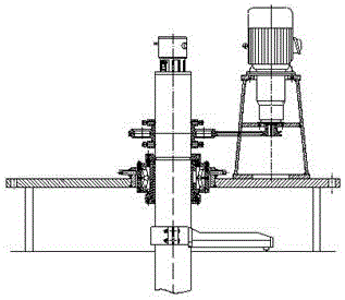
[0003] Currently, if image 3 It is a structural schematic diagram of an existing power transmission form in which the reducer drives the main shaft to rotate. It can be seen that the power transmission form of the sprocket driving the main shaft is divided into several components, which causes inconvenience to the installation, and this chain The form of wheel transmission power is easy to bring the vibration to the main shaft of the boring bar; Figure 4 It is a structural schematic diagram of another existing power transmission form in which the reducer drives the main shaft to rotate. It can be seen that this worm gear transmission mode has disadvantages such as low mechanical efficiency, difficult processing of the worm gear, and easy wear of the worm gear.

Method used


Image

  • Novel special speed reducer for boring machine
  • Novel special speed reducer for boring machine
  • Novel special speed reducer for boring machine

Examples


Embodiment Construction

[0030] The present invention will be further explained below in conjunction with the accompanying drawings and specific embodiments. It should be understood that the following specific embodiments are only used to illustrate the present invention and are not intended to limit the scope of the present invention.

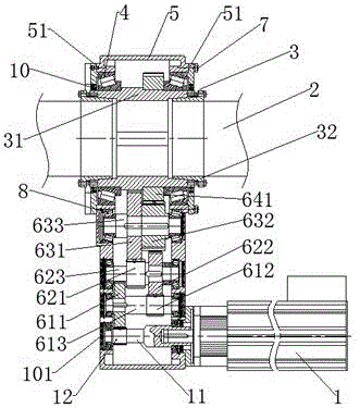
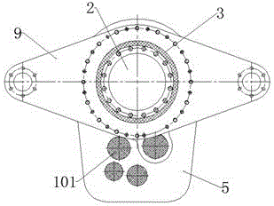
[0031] Such as figure 1 with 2 As shown, a new type of special reducer for boring and arranging, including motor (1), main shaft (2), bearing sleeve (3), first bearing (4) and The casing (5), and the transmission mechanism (6) arranged in the casing (5). The present invention adopts a compact integral layout, which reduces the assembly time of the boring row.

[0032] Among them, the bearing sleeve (3) includes the main shaft sleeve (31) and the inner sleeve (32) respectively arranged on the inside of both ends of the main shaft sleeve (31). The inner sleeve (32) is provided with a taper, and the outer surface of the inner sleeve (32) is Tapered surface, the inner...


PUM


Abstract

The invention provides a novel special speed reducer for a boring machine. The novel special speed reducer comprises a motor, a spindle, a bearing sleeve, first bearings and a shell, which are sleeved at the outside of the spindle from inside to outside, and a transmission mechanism arranged in the shell, wherein the bearing sleeve comprises a spindle sleeve and inner sleeves arranged on inner sides of both ends of the spindle sleeve, the first bearings are arranged on both ends of the outer side of the spindle sleeve, inner rings and outer rings of the first bearings are fixedly connected with the outer side of the spindle sleeve and the inner side of the shell respectively, the spindle sleeve is connected with the motor through the transmission mechanism, and the transmission mechanism comprises a fourth level transmission device, a third level transmission device, a second-level transmission device and a first-level transmission device, which are connected in sequence. The novel special speed reducer has the advantages that existing power source structure is replaced, so that the processing precision and the efficiency of the boring machine are improved, the power system is integrated, and the vibration of the spindle, the manpower consumption and the maintenance cost are reduced; the novel special speed reducer can be fixed to any position of the spindle by a torque arm board; a servo motor drives the spindle to rotate, so that the volume of the speed reducer is compact, energy is saved, the overload capacity is high, and the novel special speed reducer has the sense of science and technology.

Description

technical field [0001] The invention relates to the technical field of reducers, in particular to a new type of reducer specially used for boring and arranging. Background technique [0002] The rudder shafting boring process equipment is mainly a precision special equipment for boring cylindrical or conical holes and end faces such as rudder stock, rudder pin hole, shaft tube hole, etc. Since shipyards currently use keyless connections and hydraulic expansion installation methods for the installation of rudders and propellers, the processing technology requirements for holes are very high. This not only requires the operating accuracy of the staff, but also the performance and machining accuracy of the boring row are also very important. During the machining of the boring row, the rotating power of the boring row spindle is transmitted by the reducer. [0003] Currently, if image 3 It is a structural schematic diagram of an existing power transmission form in which the r...

Claims


Application Information

Patent Timeline
Patent Type & Authority Applications(China)
IPC IPC(8): F16H1/22F16H57/022F16H57/028
CPCF16H1/22F16H57/022F16H57/028
Inventor 陈建红肖伟张腾云
Owner JIANGSU BOLIN MACHINERY MFG
Learn More