
Method for calculating spectrum thermal radiance of multilayer optical film

A multi-layer thin film and optical thin film technology, applied in the field of spectral thermal emissivity characterization

Active Publication Date: 2017-05-10
TIANJIN JINHANG INST OF TECH PHYSICS
View PDF10 Cites 8 Cited by
  • Summary
  • Abstract
  • Description
  • Claims
  • Application Information

AI Technical Summary

Problems solved by technology

[0006] The purpose of this invention is to propose a calculation method for the spectral thermal emissivity of a multilayer optical film to solve the problem of how to reduce the cost of direct thermal radiation measurement and the complexity of the measurement device

Method used


Image

  • Method for calculating spectrum thermal radiance of multilayer optical film
  • Method for calculating spectrum thermal radiance of multilayer optical film
  • Method for calculating spectrum thermal radiance of multilayer optical film

Examples


Embodiment

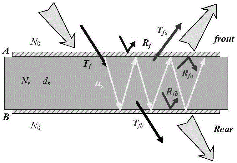
[0157] This embodiment selects the double-sided anti-reflection film of zinc sulfide substrate, such as figure 1 shown. The substrate thickness of zinc sulfide is selected as 5mm, and the thermal radiation characteristics of the multilayer film A-substrate-multilayer film B system are calculated at room temperature in the range of 7.5μm-9.7μm. The thin film materials are germanium and yttrium fluoride respectively, and the film systems of interface A and interface B are as follows:

[0158] ZnS|0.5298H 0.1411L 1.0932H 0.5478M 0.2883L 0.3019M|Air

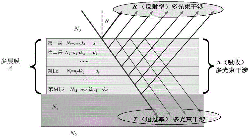
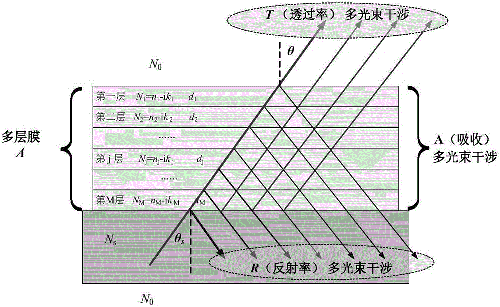
[0159] Among them, λ 0 =8 μm, H is germanium, L is yttrium fluoride, and M is zinc sulfide. The forward and backward propagation characteristics of light waves at interface A and interface B are as follows: figure 2 with image 3 shown.

[0160] The base material is chosen as zinc sulfide, whose optical constants are as Figure 4 shown. The thin film materials are germanium and yttrium fluoride, respectively, and their optic...


PUM


Abstract

The invention belongs to the field of spectrum thermal radiance representation, and specifically relates to a method for calculating the spectrum thermal radiance of a multilayer optical film. The method is simple and feasible. For a determined multilayer film-substrate-multilayer film system structure, the method can completely express the spectrum directional radiance, directional radiance, spectrum radiance and integral spatial radiance of an optical multilayer film with only one need to determine the thermo-optical coefficients of a substrate and a film material. The method can avoid the tedious operation of direct measurement and a complex structure design of a measuring instrument, and has a certain scientific and application value.

Description

technical field [0001] The invention belongs to the field of spectral thermal emissivity characterization, and in particular relates to a method for calculating the spectral thermal emissivity of a multilayer optical film. Background technique [0002] With the development of infrared photoelectric technology, the passive photoelectric detection and imaging system based on target infrared radiation has become an important basic technology in the field of basic science and application technology, such as infrared thermal imager, infrared radiation thermometer, infrared high-resolution spectrometer, Infrared imaging guidance system, etc. In the field of aerospace applications, infrared optoelectronic devices represented by infrared imaging guidance systems are widely used in aircraft. [0003] In recent years, as the flight speed of the flight system develops from subsonic speed to hypersonic speed, the aircraft with infrared imaging device flies at high speed in the dense at...

Claims


Application Information

Patent Timeline
Patent Type & Authority Applications(China)
IPC IPC(8): G01J5/00
CPCG01J5/0003G01J5/802
Inventor 刘华松刘丹丹杨霄姜承慧陈丹季一勤
Owner TIANJIN JINHANG INST OF TECH PHYSICS
Learn More