System and method for debugging single-mode broadband double-fiber collimator and thereof

A dual-fiber collimator and debugging system technology, applied in optics, instruments, optical components, etc., can solve problems such as insufficient debugging of one-dimensional adjustment frames, slow debugging, slow start of new employees, etc.

Active Publication Date: 2017-05-10
上海中科光纤通讯器件有限公司 +2
View PDF5 Cites 5 Cited by
  • Summary
  • Abstract
  • Description
  • Claims
  • Application Information

AI Technical Summary

Problems solved by technology

There are too many factors that affect the coupling insertion loss in this method. The melting loss of the fusion splicer is too large, the fiber cutting end face is bad, the lens end face is dirty or the lens i...

Method used


Image

  • System and method for debugging single-mode broadband double-fiber collimator and thereof
  • System and method for debugging single-mode broadband double-fiber collimator and thereof
  • System and method for debugging single-mode broadband double-fiber collimator and thereof

Examples


Embodiment Construction

[0070] In order to be able to understand the technical content of the present invention more clearly, the following embodiments are specifically described in detail.

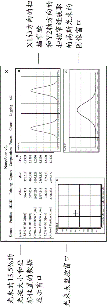
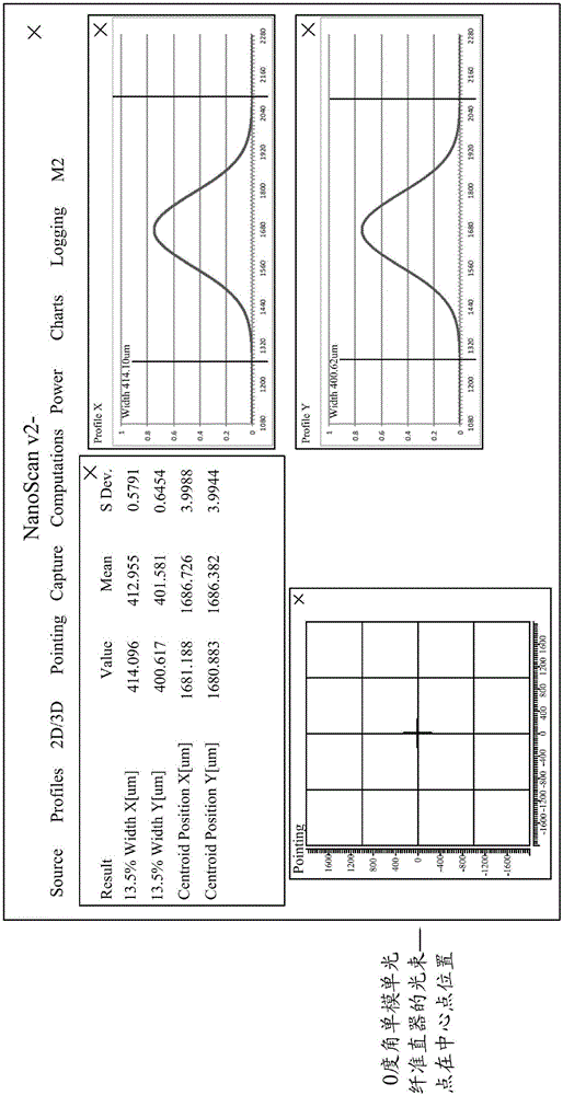
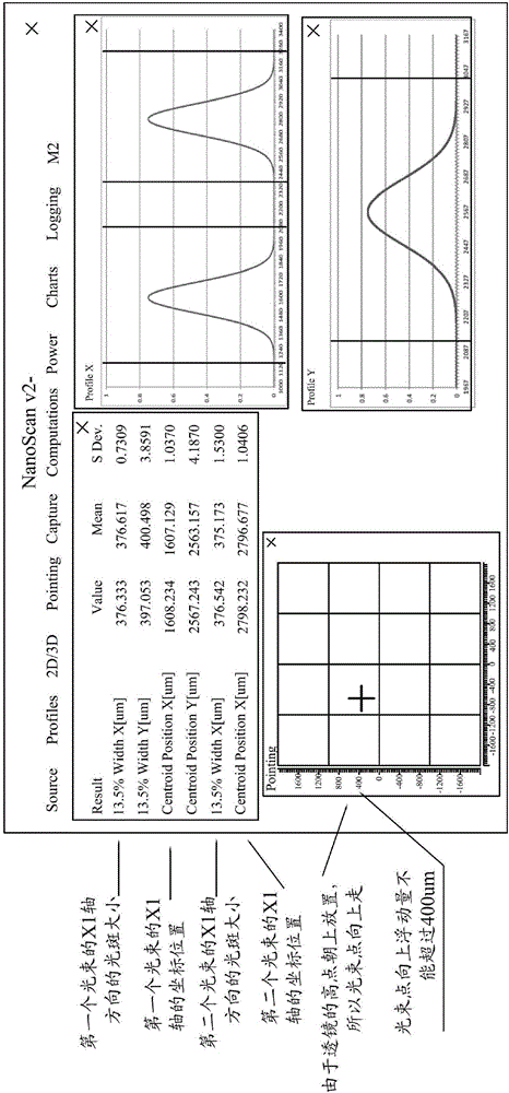
[0071] See figure 2 , Image 6 , Figure 7 with Figure 8 , A single-mode broadband dual-fiber collimator debugging system, including a light source, an adjustment frame, a single-mode broadband dual-fiber collimator to be debugged, and a spot machine, wherein the single-mode broadband dual-fiber collimator to be debugged The optical fiber collimator includes a single-mode dual-fiber pigtail, a lens and an outer tube. The single-mode dual-fiber pigtail is movably installed on an adjustment platform of the debugging system, and the lens is glued to One end of the outer sealing tube is fixedly installed on the adjustment platform through the outer sealing tube, and the lens and the single-mode broadband dual-fiber pigtail are in the same straight line, and the spot machine includes a The probe is movably installed a...


PUM

PropertyMeasurementUnit
Wavelengthaaaaaaaaaa

Abstract

The invention relates to a system and method for debugging a single-mode broadband double-fiber collimator. The system for debugging the single-mode broadband double-fiber collimator comprises an FP-LD laser light source with a wavelength of 1550nm, a Photon Nano Scan spot device, a one-dimensional adjusting bracket, a five-dimensional adjusting bracket, a computer and a to-be-debugged single-mode broadband double-fiber collimator, wherein the FP-LD laser light source with a wavelength of 1550nm is arranged at one end of the single-mode broadband double-fiber collimator; the to-be-debugged single-mode broadband double-fiber collimator is arranged on the one-dimensional adjusting bracket on the five-dimensional adjusting bracket; the one-dimensional adjusting bracket is used for adjusting a clearance between a single-mode double-fiber pigtail and a lens in the single-mode broadband double-fiber collimator; the Photon Nano Scan v2 spot device is interconnected with the computer; the debugging of the single-mode broadband double-fiber collimator is realized by debugging the five-dimensional adjusting bracket; the spot device is used for double beam debugging. The debugging method according to the invention is simple and convenient in operation, high in debugging result consistency, low in insertion loss and high in yield, and can be widely applied to the field of optical fiber communication.

Description

Technical field [0001] The invention relates to the field of manufacturing methods for single-mode broadband dual-fiber collimators, in particular to the debugging technology of single-mode broadband installed fiber collimators, and specifically refers to a single-mode broadband dual-fiber collimator debugging system and method. Background technique [0002] At present, the common manufacturing method of single-mode broadband dual-fiber collimator is generally to use the mirror of the corresponding wavelength range to be placed at the image side focus of the lens calculated at a certain wavelength point or at a certain distance for debugging; because of the waveband 1260~1620nm is the common wavelength band of optical communication, so the dual wavelength points of 1310nm and 1550nm are selected for debugging and monitoring to meet this broadband requirement. Use the fusion splicer, cutting knife and wire stripper to connect the single-mode broadband dual-fiber collimator to be d...

Claims


Application Information

Patent Timeline
IPC IPC(8): G02B27/62G02B27/30
CPCG02B27/30G02B27/62
Inventor 叶雪梅
Owner 上海中科光纤通讯器件有限公司
Why Eureka
Try Eureka