Direct-writing type silk screen plate-making equipment and use method therefor

A screen plate making and direct writing technology, applied in the field of direct writing screen plate making equipment, can solve the problems of uneven energy distribution, short service life, uneven energy output distribution of digital micromirror devices, etc.

Active Publication Date: 2017-05-10
ADVANCED DIGITAL SCREEN SYST INC
View PDF13 Cites 6 Cited by
  • Summary
  • Abstract
  • Description
  • Claims
  • Application Information

AI Technical Summary

Problems solved by technology

[0002] In the existing laser direct writing equipment, the displacement sensor next to the exposure point is generally used to measure the distance between the optical lens and the screen at the exposure point position. Although the exposure point position is close to the displacement sensor, there is a short distance between them, but They are not actually in the same position; therefore, the distance measured by the displacement sensor is not the actual distance from the optical lens to the screen, although they are very close in most cases
[0003] In the prior art, the above-mentioned measured distance is used to adjust the focal plane of the optical lens at the exposure point, because the assembly position of the displacement sensor is inconsistent with the position of the exposure point, and using the distance measured by the displacement sensor to adjust the focal plane of the optical lens will lead to errors
[0004] In addition, in the existing laser direct writing equipment, the digital micromirror device is often used on the whole page. Since the digital micromirror device is composed of a large number of micromirrors, when the function of some micromirrors fails, the entire digital micromirror device is scrapped, resulting in digital micromirror devices. The disadvantages of low utilization rate of mirror devices and relatively short service life
[0005] In addition, in the existing laser direct writing equipment, during the scanning process of the digital micromirror device, on the scanning track of each micromirror point, the energy distribution of each track is uneven, resulting in the distribution of energy output on the digital micromirror device. uneven problem
Affect image exposure quality

Method used


Image

  • Direct-writing type silk screen plate-making equipment and use method therefor
  • Direct-writing type silk screen plate-making equipment and use method therefor
  • Direct-writing type silk screen plate-making equipment and use method therefor

Examples


Embodiment 1

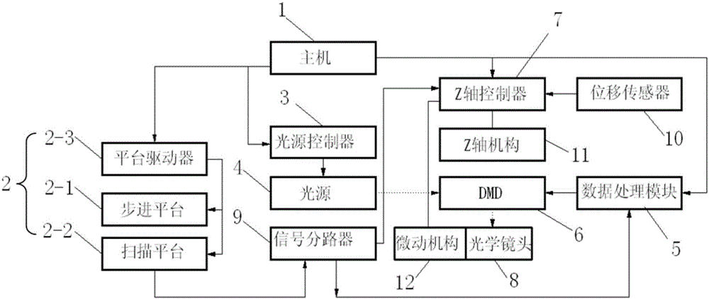
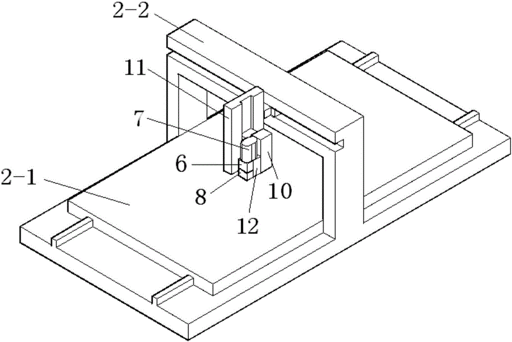
[0076] Refer to attached figure 1 And attached figure 2 , a direct-writing screen plate-making equipment, used for the plate-making process of screen printing, including a host 1, a motion system 2, a light source controller 3, a light source 4, a data processing module 5, a digital micromirror device 6, and a Z-axis control Device 7, optical lens 8, signal splitter 9, displacement sensor 10, Z-axis mechanism 11 and micro-motion mechanism 12;

[0077] The motion system 2 is composed of a stepping platform 2-1, a scanning platform 2-2 and a platform driver 2-3; wherein the platform driver 2-3 is connected with the host computer 1 for driving the stepping platform 2-1 and the scanning platform. platform 2-2 movement;

[0078] Described light source controller 3 is connected with main frame 1 and controls the switching status and light intensity of light source 4, and light source 4 is the light energy of continuous output that digital micromirror device 6 provides, and the li...

Embodiment 2

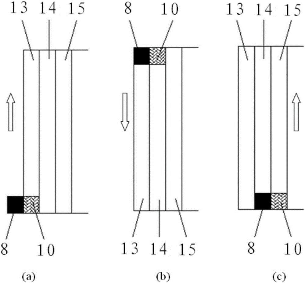
[0087] Refer to attached Figure 4 (b), attached Figure 4 (b) The scanning direction of the digital micromirror device 6 forms an included angle θ with the row direction of the entire array of micromirrors in the digital micromirror device. To repeat once, the image area 20 to be scanned is divided into subdivision blocks with a pitch of pw2, pw2=d×sinθ;

[0088] Refer to attached Figure 4 (a), attached Figure 4 (b) There is no angle between the scanning direction of the digital micromirror device 6 and the row direction of the entire array of micromirrors in the digital micromirror device, and the image area 20 to be scanned is divided into subdivided blocks with a pitch of pw1, pw1=d, because pw2=d×sinθ, obviously pw2 is less than pw1, when the scanning direction of the digital micromirror device 6 and the row direction of the micromirrors in the digital micromirror device form an included angle θ, the image area 20 to be scanned is divided More detailed, high data re...

Embodiment 3

[0101] The inclined laser direct writing technology cannot directly use the TIF image used in the printing field. The existing technology is to enlarge the image, but the amount of calculation and data in this process is extremely large. Compared with the prior art, the amount of computation and data in the processing process of this embodiment is small, and the obtained graphics have high resolution, which is conducive to the low-load operation of the equipment, and can improve the pattern refresh rate of the digital micromirror device (DMD).

[0102] In this embodiment, the TIF image is converted into a vector diagram, and the specific implementation process adopts the following process.

[0103] Refer to attached figure 1 , the TIF image processing method on the direct-write screen plate-making equipment is divided into the following steps:

[0104] (a) First install image processing software in host 1;

[0105] (b) setting the path and image processing parameters of the ...


PUM

PropertyMeasurementUnit
Angleaaaaaaaaaa

Abstract

The invention discloses direct-writing type silk screen plate-making equipment and a use method therefor. In the prior art, the problem of inconsistency between a measured focal plane and an actual focal plane caused by position offset between a displacement sensor and an exposure point in assembling exists. The invention provides the direct-writing type silk screen plate-making equipment and a focal plane control method; a mapping relation between a focal plane position of a scanning band to be scanned in a next step and a scanning platform position signal is pre-established by a Z-axis controller; and in the next step of scanning, the position of an optical lens is adjusted according to the mapping relation, so that the problem of inconsistency between a measured focal plane and an actual focal plane caused by position offset between the displacement sensor and the optical lens in assembling can be avoided. The invention also provides an exposure method through a perceptual region and a method for realizing online real-time optical uniformity compensation, so that the problems of shortening of service life of a digital micromirror device and uneven energy output distribution on the digital micromirror device are solved.

Description

technical field [0001] The invention relates to the technical field of screen plate making, in particular to a direct-writing screen plate making device and a method for using the same. Background technique [0002] In the existing laser direct writing equipment, the displacement sensor next to the exposure point is generally used to measure the distance between the optical lens and the screen at the exposure point position. Although the exposure point position is close to the displacement sensor, there is a short distance between them, but They are not actually in the same position; therefore, the distance measured by the displacement sensor is not the actual distance from the optical lens to the stencil, although they are very close in most cases. [0003] In the prior art, the above-mentioned measured distance is used to adjust the focal plane of the optical lens at the exposure point, because the assembly position of the displacement sensor is inconsistent with the posit...

Claims


Application Information

Patent Timeline
IPC IPC(8): G03F7/20
CPCG03F7/2055G03F7/70383G03F7/70508B41C1/145G03F7/12G03F7/2057G03F7/70291G03F9/7026G03F7/70275G03F7/70591G03F7/70641
Inventor 吴景舟马迪陈修涛王运钢董辉李泽忠其他发明人请求不公开姓名
Owner ADVANCED DIGITAL SCREEN SYST INC
Why Eureka
Try Eureka