Sensorless control method of permanent magnet synchronous motor

A technology of permanent magnet synchronous motor and control method, applied in the direction of motor generator control, electronic commutation motor control, control system, etc., can solve the problems of low reliability, poor dynamic and static performance, complex algorithm, etc., to increase reliability , improve dynamic performance, low complexity effect

Active Publication Date: 2017-05-10
HEFEI UNIV OF TECH
View PDF7 Cites 18 Cited by
  • Summary
  • Abstract
  • Description
  • Claims
  • Application Information

AI Technical Summary

Problems solved by technology

[0008] The technical problem to be solved by the present invention is to provide a position sensorless control method for permanent magnet synchronous motors for the problems of poor dynamic and static performance, low reliability and complex algorithms in the zero-speed and low-speed position identification of permanent magnet synchronous motors , inject the pulsating high-frequency voltage signal into the motor, sample the stator winding current, and estimate the position and speed of the motor rotor from the high-frequency current response

Method used


Image

  • Sensorless control method of permanent magnet synchronous motor
  • Sensorless control method of permanent magnet synchronous motor
  • Sensorless control method of permanent magnet synchronous motor

Examples


Embodiment Construction

[0051] The specific implementation manners of the present invention will be described below in conjunction with the accompanying drawings.

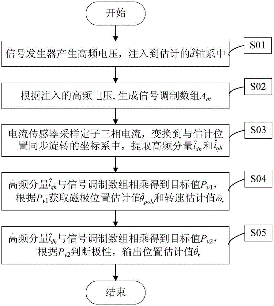
[0052] figure 1 It is a flow chart of the method of the present invention, and it can be seen from the figure that the present invention includes the following steps.

[0053] Step 1 (S01), the signal generator generates a high-frequency voltage signal v h , and injected into the estimated In the shaft system, v h As shown in the following formula:

[0054] v h =V h sin(ω h t+π)

[0055] Among them, V h is the high-frequency voltage amplitude, ω h is the high-frequency voltage angular frequency, and t represents the signal injection time.

[0056] Step 2 (S02), according to the high-frequency voltage signal v injected in step 1 h , calculate the signal modulation array A m The dimension N, generate signal modulation array A m .

[0057] Step 3 (S03), the current sensor samples the stator winding current i a i b and i c ,...


PUM


Abstract

The invention discloses a sensorless control method of a permanent magnet synchronous motor, and belongs to the field of motor control. In the method, a pulsating high frequency voltage signal is injected, and the position and rotating speed of a motor rotor are estimated from high frequency current response. The method comprises the following steps of: generating a high frequency voltage signal vh and injecting the high frequency voltage signal in an estimated (the formula is described in the specification) shaft system, generating a signal modulation array Am; sampling the current of a stator winding by a current sensor, performing coordinate transformation, and extracting high frequency components (the formula is described in the specification) and (the formula is described in the specification); multiplying (the formula is described in the specification) with the signal modulation array Am to obtain a target value Pv1, and obtaining a magnetic pole position estimated value (the formula is described in the specification) and a rotating speed estimated value (the formula is described in the specification); multiplying (the formula is described in the specification) with the signal modulation array Am to obtain a target value Pv2, judging the polarity of a magnetic pole, compensating (the formula is described in the specification), and outputting a rotor position estimated value (the formula is described in the specification). By virtue of the method, the position identification during zero speed and low speed can be realized, no filter is used in the identification process, the system stability and the identification precision are improved, and the dynamic performance is improved; a saturated working point is selected according to the motor power, and the reliability of polarity judgment is improved; the algorithm complexity is low, and digital realization is easy.

Description

technical field [0001] The invention relates to a position sensorless control algorithm of a permanent magnet synchronous motor, belonging to the field of motor control. Background technique [0002] Permanent magnet synchronous motors are widely used in electric vehicles, wind power, and servo fields due to their high power density, high efficiency, and excellent operating performance. In order to realize the high-performance vector control of the electric drive system, the position information of the motor rotor must be obtained accurately. The position can be detected by using a photoelectric encoder or a resolver, but the mechanical sensor increases the system cost and the risk of failure, so the research on the algorithm without a position sensor is of great significance. [0003] The rotor position identification algorithm of permanent magnet synchronous motor is mainly divided into two categories, one is to use the back EMF of the motor, and the other is to use the s...

Claims


Application Information

Patent Timeline
Patent Type & Authority Applications(China)
IPC IPC(8): H02P21/14H02P21/18
CPCH02P21/14
Inventor 张兴李浩源杨淑英谢震杨健李二磊刘威
Owner HEFEI UNIV OF TECH
Why Eureka
Try Eureka