
Tunable filter and tunable filter array

A tuning filter and array technology, applied in the field of micro-electromechanical systems and optical filtering, can solve complex computing requirements and other problems, achieve high sensitivity, large cavity length tuning, and easy integration

Active Publication Date: 2019-01-22
SHENZHEN INST OF ADVANCED TECH +1
View PDF7 Cites 1 Cited by
  • Summary
  • Abstract
  • Description
  • Claims
  • Application Information

AI Technical Summary

Problems solved by technology

Traditional spectroscopic techniques use dispersive (prism, grating) spectroscopic, interferometric (Fourier transform) spectroscopic, and these systems form spectrometers that weigh hundreds of pounds or have complex computational requirements
As the technical specifications of imaging spectrometers are getting higher and higher, mainly in terms of spatial resolution, spectral resolution, and weak signal detection capabilities, imaging spectrometers with traditional (dispersion, interference) spectroscopic techniques are gradually unable to meet the requirements. And due to the development of infrared focal plane array technology, traditional spectroscopic elements are not suitable for the development of focal plane technology. Therefore, the development of filter spectroscopic devices compatible with focal plane technology is an important development direction in the industry.

Method used


Image

  • Tunable filter and tunable filter array
  • Tunable filter and tunable filter array
  • Tunable filter and tunable filter array

Examples


Embodiment 1

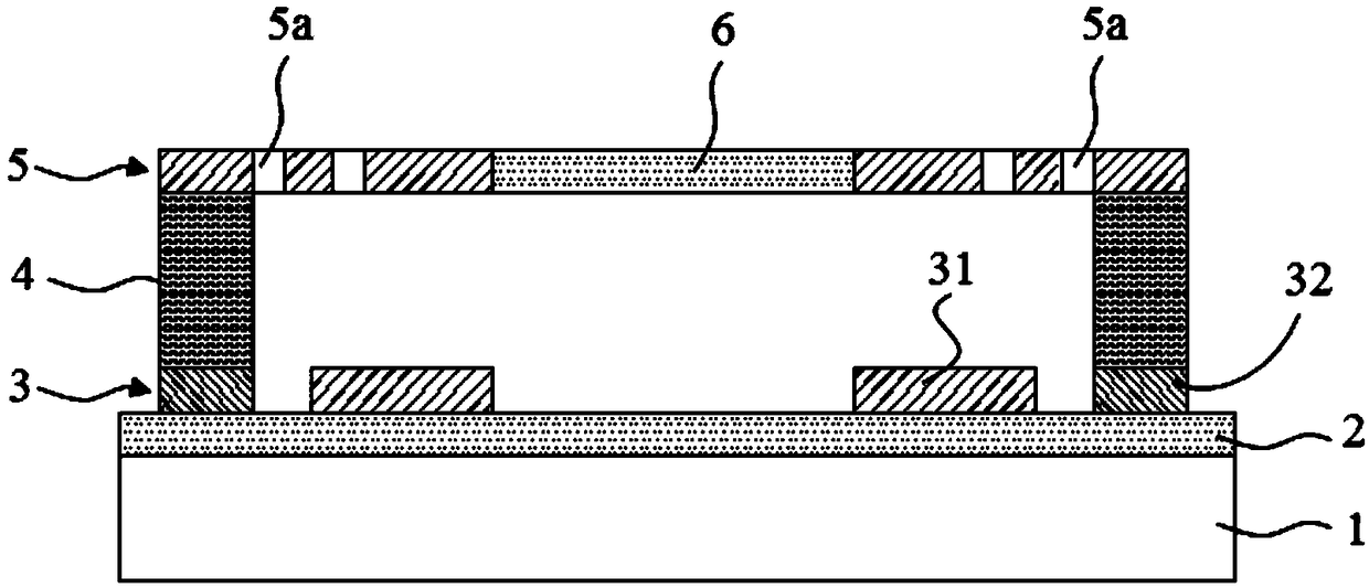
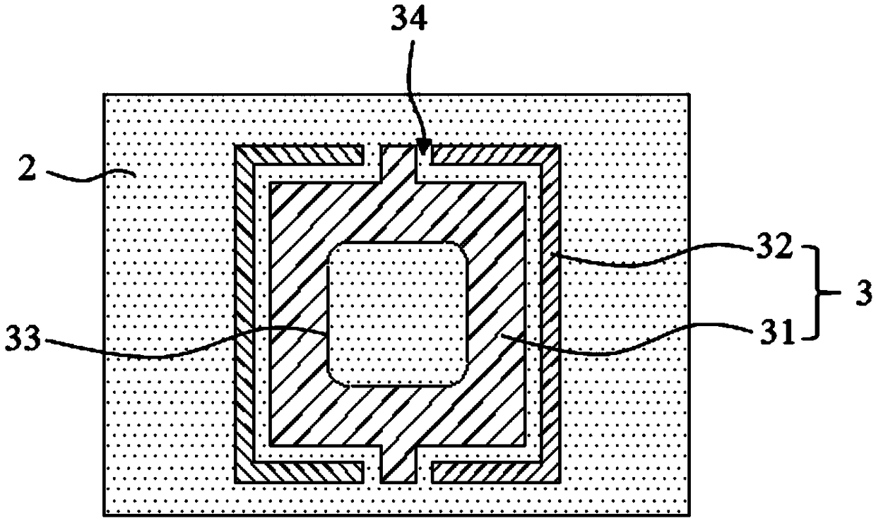
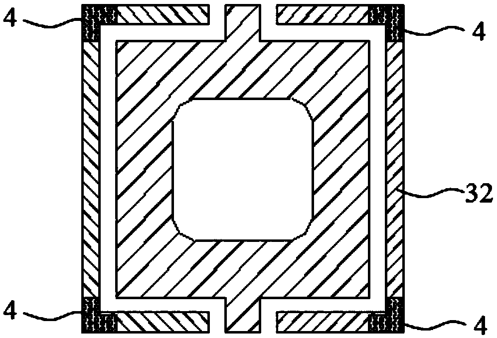
[0040] refer to Figure 1 to Figure 5 , this embodiment provides a tunable filter. like figure 1 As shown, the tunable filter mainly includes a semiconductor substrate 1 , a first reflection plane 2 , a bottom electrode 3 , a support element 4 , a metal bridge 5 and a second reflection plane 6 .

[0041] Wherein, the first reflective plane 2 is formed on the semiconductor substrate 1 . The bottom electrode 3 includes a first electrode 31 and a second electrode 32 electrically insulated from each other, formed on the first reflective plane 2 . The supporting element 4 is connected to the second electrode 32 . The metal bridge deck 5 is supported by the supporting element 4 and opposite to the bottom electrode 3 , and is electrically connected to the second electrode 32 through the supporting element 4 . The second reflective plane 6 is arranged in the metal bridge deck 5 and is exposed from the side of the metal bridge deck 5 facing the first reflective plane 2, thus, the f...

Embodiment 2

[0051] This embodiment provides a tunable filter array, such as Image 6 As shown, the tunable filter array includes a substrate 10 with a readout circuit and a plurality of tunable filters 20 arrayed on the substrate, wherein the tunable filter 20 adopts the embodiment The tunable filter provided in 1.

[0052] Wherein, the readout circuit in the substrate 10 can be selected as a CMOS readout circuit, and each tunable filter 20 can be individually controlled by the CMOS readout circuit. A plurality of tunable filters 20 are arranged in an array to realize a filter of a large area array. For example, in this embodiment, the size of each tunable filter 20 is 100 μm×100 μm, and the tunable filter array includes 384×288 Tunable filter 20. It should be noted that the attached Image 6 Only several tunable filters 20 are exemplarily shown in the figure, and in some other embodiments, other numbers (M rows×N columns) of tunable filters 20 may also be set according to actual needs...


PUM


Abstract

The invention discloses a tunable filter. The tunable filter comprises a semiconductor substrate, a first reflection plane, a bottom electrode, a support element, a metal deck, and a second reflection plane. The first reflection plane is arranged on the semiconductor substrate; the bottom electrode comprises a first electrode and a second electrode which are electrically insulated, and the bottom electrode is formed on the first reflection plane; the support element is arranged on the second electrode, and is used to support the metal deck and electrically connects the metal deck to the second electrode; the metal deck is supported by the support element and is arranged opposite to the bottom electrode, the metal deck is a maze shaped cantilever frame structure that is rotationally symmetric concerning the central point; the second reflection plane is arranged in the metal deck and is exposed at the side facing the first reflection plane. The invention also discloses a tunable filter array, the array comprises a substrate with a readout circuit; the array is provided with a plurality of tunable filters on the substrate, wherein the tunable filter is a tunable filter as described previously.

Description

technical field [0001] The invention belongs to the technical field of micro-electromechanical systems, relates to the technical field of optical filtering, and in particular relates to a tunable filter and a filter array. Background technique [0002] The traditional camera obtains the geometric image information of the target. With the development of optical technology, people put forward the concept of spectral imaging. Imagers and spectrometers are two different types of optical instruments. The spectral imaging technology combines imaging technology and spectral technology to obtain the target's spectral information while obtaining the two-dimensional spatial information of the target. Imaging spectroscopy technology is a comprehensive technology integrating detector technology, precision optical machinery, weak signal detection, computer technology, and information image processing technology. An imaging spectrometer is an optical sensor that acquires three-dimensiona...

Claims


Application Information

Patent Timeline
Patent Type & Authority Patents(China)
IPC IPC(8): B81B7/02G01J3/28G01N21/01
CPCB81B7/02G01J3/2823G01N21/01
Inventor 蒙庆华陈四海魏广路李元元陈巍
Owner SHENZHEN INST OF ADVANCED TECH
Learn More