Surface modification mask plate, manufacturing method thereof and manufacturing method of electroluminescence device
A technology of surface modification and production method, which is applied in the field of optics, can solve the problems of expensive equipment investment, and achieve the effect of improving orientation and reducing costs
- Summary
- Abstract
- Description
- Claims
- Application Information
AI Technical Summary
Problems solved by technology
Method used
Image

Examples
Embodiment 1
[0045] The steps of the method for fabricating a surface-modified mask provided in this embodiment include:
[0046] Step S01, immersing the mask in a solution with a hydrophobic material, the hydrophobic material being heptadecafluorodecyltrimethoxysilane, so that the hydrophobic material is fixed on the surface of the mask;
[0047] Step S02, separating the mask plate immobilized with the hydrophobic material from the solution, and drying the mask plate;
[0048] Step S03, placing the first mask on the first surface of the mask plate with 96×64 hollowed-out parts, the first mask is composed of 96×64 first shielding parts and first transparent parts connecting each first shielding part. Composition of light parts, the first shielding part corresponds to the hollow part one by one, and the area of each first shielding part in one-to-one correspondence is larger than the area of each hollow part, and the UV lamp is used to emit ultraviolet light with a wavelength of 185nm a...
Embodiment 2
[0050] The steps of the method for fabricating a surface-modified mask provided in this embodiment include:
[0051] Step S01, immersing the mask in a solution with a hydrophobic material, the hydrophobic material being heptadecafluorodecyltrimethoxysilane, so that the hydrophobic material is fixed on the surface of the mask;
[0052] Step S02, separating the mask plate immobilized with the hydrophobic material from the solution, and drying the mask plate;
[0053] Step S03, placing the second photomask on the mask plate with 96×64 hollowed-out parts, the second photomask is composed of 96×64 second light-transmitting parts and a second shielding part connecting the second light-transmitting parts , the second light-transmitting part corresponds to the hollow part one-to-one, and the area of each second light-transmitting part in one-to-one correspondence is larger than the area of each hollow part, and a UV lamp is used to emit ultraviolet light with a wavelength of 185nm...
Embodiment 3
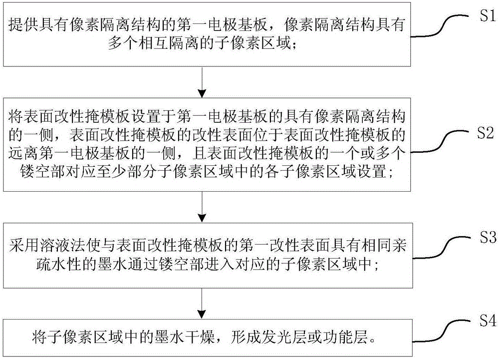
[0055] The fabrication method of the electroluminescent device provided in this embodiment comprises the following steps:
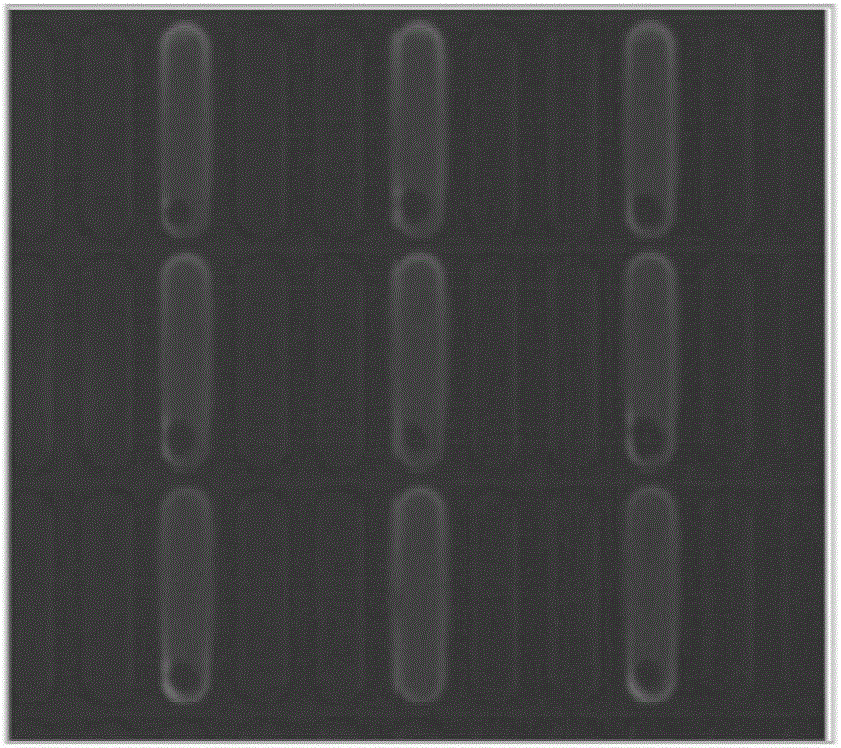
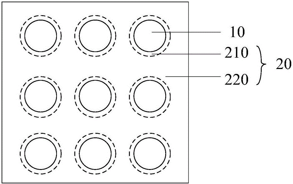
[0056] Step S1, providing a first electrode substrate with a pixel isolation structure, the pixel isolation structure has 96×64 mutually isolated sub-pixel regions, the first electrode substrate is a substrate with an anode layer, and the anode layer is an ITO anode;
[0057] In step S2, the surface modification mask provided in Example 2 is placed on the side of the first electrode substrate having the pixel isolation structure, the hollow part of the surface modification mask corresponds to the sub-pixel area, and the surface modification mask It has a modified surface including a hydrophilic surface and a hydrophobic surface, the hydrophilic surface surrounds the hollow part, and the modified surface other than the hydrophilic surface is a hydrophobic surface;
[0058] Step S3, using an inkjet printing (model Dimatix Materials Printer DMP-2831) process...
PUM
 Abstract
Description
Claims
Application Information
 - Generate Ideas
- Intellectual Property
- Life Sciences
- Materials
- Tech Scout
- Unparalleled Data Quality
- Higher Quality Content
- 60% Fewer Hallucinations
Browse by: Latest US Patents, China's latest patents, Technical Efficacy Thesaurus, Application Domain, Technology Topic, Popular Technical Reports.
© 2025 PatSnap. All rights reserved.Legal|Privacy policy|Modern Slavery Act Transparency Statement|Sitemap|About US| Contact US: help@patsnap.com