Planar slot array antenna

A technology of slot array antenna and flat plate, which is applied in the direction of antenna, antenna array, leaky waveguide antenna, etc., can solve the problems of metal contact requirements of slot leaky wave, insufficient bandwidth of air waveguide, and not suitable for mass production, etc., to reduce slot leakage wave, improved impedance matching performance, and high bandwidth effects

Pending Publication Date: 2017-05-24
GUANGDONG SHENGLU TELECOMM TECH
View PDF5 Cites 14 Cited by
  • Summary
  • Abstract
  • Description
  • Claims
  • Application Information

AI Technical Summary

Problems solved by technology

However, the bandwidth of traditional air waveguides is not wide enough, and it is difficult to meet the high-bandwidth requirements of 5G high-frequency bands. At present, the relative bandwidth of products is generally 10%-15%, and the return loss within its bandwidth is also high, and the standing wave ratio is around 2.0. , while some products sacrifice return loss in order to achieve 20% relative bandwid

Method used


Image

  • Planar slot array antenna
  • Planar slot array antenna
  • Planar slot array antenna

Examples


Embodiment Construction

[0019] The technical solution will be described in detail below in conjunction with specific embodiments.

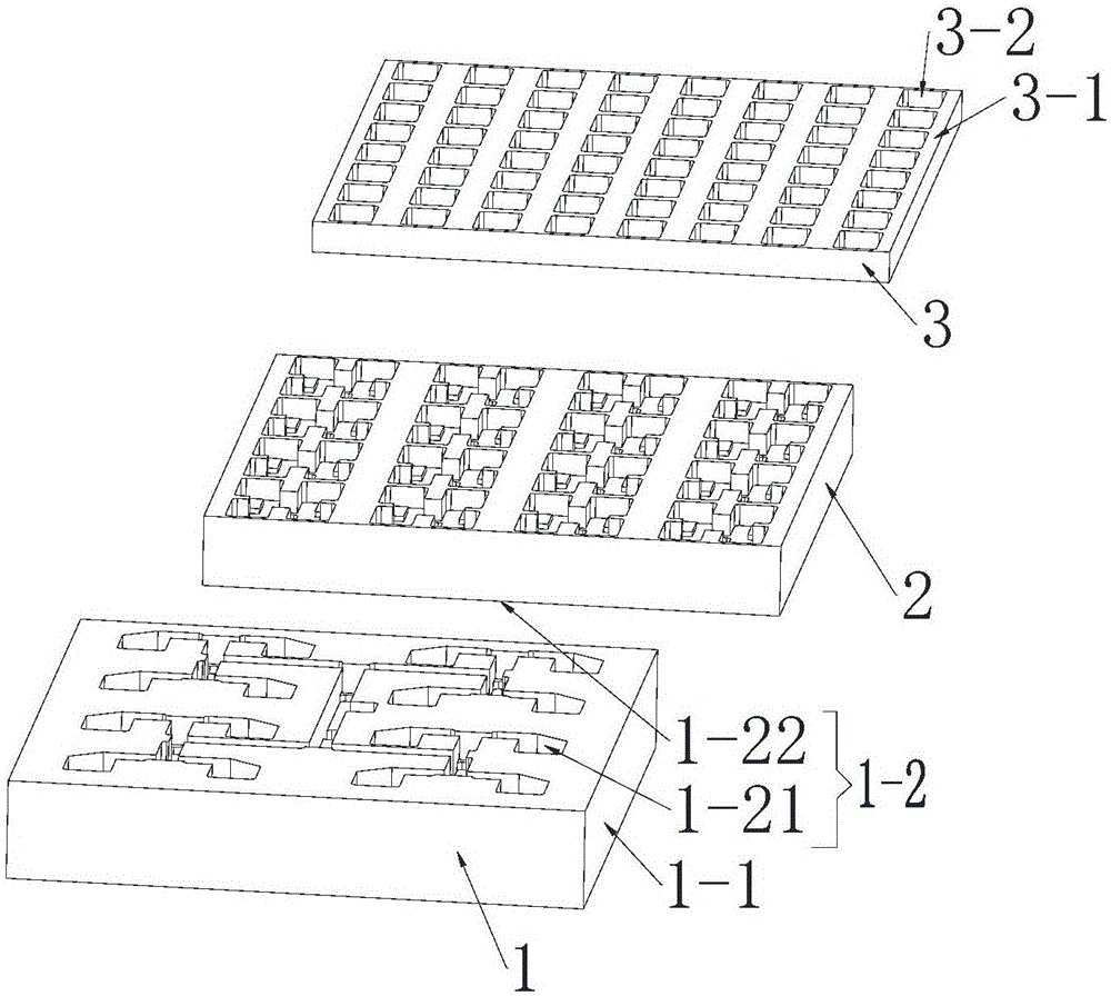
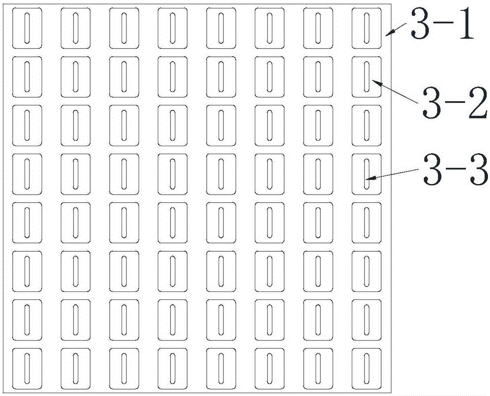
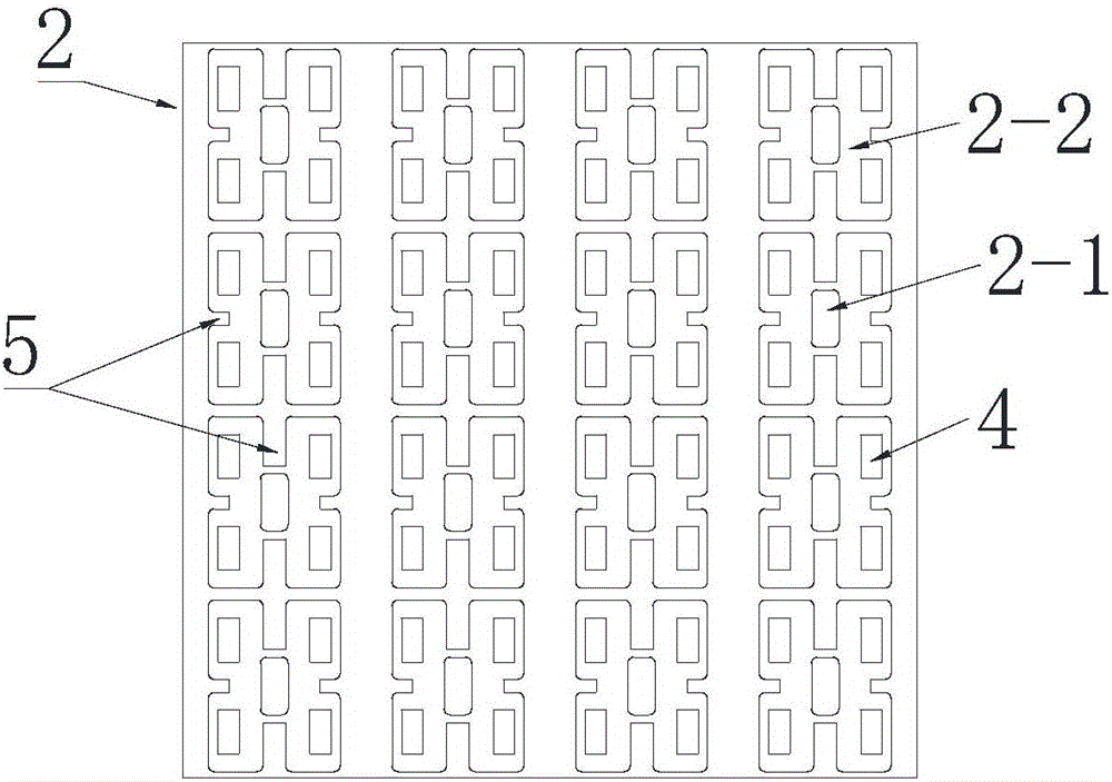
[0020] Such as Figure 1-Figure 4 As shown, the present invention is a flat panel slot array antenna, which includes a feed layer 1 containing a lower cut surface 1-22 of a feed structure, a coupling port 2-1, and a coupling cavity 2-2 arranged sequentially from bottom to top The coupling layer 2 and the radiation layer 3 of the cut surface 1-21 on the feed structure, the feed layer 1 includes a bottom plate 1-1 as the lower wall of the feed layer and an E-plane waveguide 1-2 corresponding to the bottom plate, and the E-plane waveguide adopts The H-plane center cut combination method forms the upper and lower cut surfaces 1-21 and 1-22 of the E-plane waveguide transmission layer. The metal contact requirements are not high, which can greatly reduce the gap leakage wave, and the processing accuracy and cost are low. , can be mass-produced by machining or mold opening, an...


PUM


Abstract

The invention discloses a planar slot array antenna which is characterized in that the antenna comprises a feeding layer containing a feeding structure, a coupling layer containing a coupling port and a coupling cavity, and a radiating layer, which are arranged in sequence from bottom to top; the feeding layer adopts an E-plane waveguide, the E-plane waveguide is coupled to the upper coupling layer via an aperture by a T-type equal-amplitude in-phase power divider, the coupling cavity is arranged above the coupling port of the coupling layer, and a one-four power divider is formed; and a radiating slot array composed of multiple radiating slot units is arranged in the radiating layer, and steps are arranged in positions corresponding to the radiating slot units in the coupling cavity. The planar slot array antenna is simple in structure, has the characteristics of high bandwidth and low loss, and is superior to products of the same type in performance.

Description

technical field [0001] The invention relates to the technical field of antennas, in particular to a flat panel array antenna. Background technique [0002] With the rapid development of antenna technology and the comprehensive popularization of the information society, in 2020 and in the future, mobile communication technology will enter the development stage of the fifth generation mobile communication (5G). It is characterized by 0.1-1Gbps experience rate, several 10Tbps / km 2 Traffic density, million-level connection density, low power consumption, etc. The basic requirements of the 5G network for the antenna technology field are mainly high bandwidth and low loss, while the application aspects are millimeter wave planar array (mmWave planar array), multi-unit (massive MIMO), beam forming (beam forming), beam scanning (beam scanning) steering), multi-beam and active integrated phased array (phase control array). Among them, the millimeter-wave flat panel array plays a v...

Claims


Application Information

Patent Timeline
IPC IPC(8): H01Q13/20H01Q21/00H01Q21/06H01Q1/50
CPCH01Q13/20H01Q21/0018H01Q21/0037H01Q21/068
Inventor 刘沛业陈志兴章玉涛
Owner GUANGDONG SHENGLU TELECOMM TECH
Why Eureka
Try Eureka