
Carbon anode roasting fume purification ultra-low emission system and process

A technology for flue gas purification and carbon anode, which is used in gas treatment, chemical instruments and methods, combined devices, etc., can solve the problems of difficulty in releasing electric charges, waste of energy, deterioration of purification performance, etc., to increase the specific dust collection area, improve Purification efficiency, the effect of increasing corona density

Pending Publication Date: 2017-05-31
高国纯
View PDF10 Cites 3 Cited by
  • Summary
  • Abstract
  • Description
  • Claims
  • Application Information

AI Technical Summary

Problems solved by technology

Anode: still use the outdated Φ20mm-Φ40mm gas pipe row tube type anode plate (the backward technology of the original electric tar catcher in Japan in the 1970s), the asphalt smoke is difficult to charge, and the pre-charged asphalt tar dust adheres to the When the anode tubes of Φ20mm-Φ40mm are arranged, it is very difficult to release the charge. As a result, the voltage of the electric field decreases, the current increases, frequent short-circuit discharges, and the purification performance deteriorates significantly, resulting in a short-circuit of the electric field of the electric tar catcher, resulting in the failure of the equipment to operate
Equipment with this type of structure wastes energy, the technology is backward, and various pollutant discharge indicators cannot meet the requirements of the country's new new energy emission indicators.
And there is no SO in the existing carbon roasting flue gas purification system 2 , F (solid) and nitride purification device

Method used


Image

  • Carbon anode roasting fume purification ultra-low emission system and process
  • Carbon anode roasting fume purification ultra-low emission system and process
  • Carbon anode roasting fume purification ultra-low emission system and process

Examples


Embodiment Construction

[0049] Embodiments of the present invention are further described below in conjunction with the accompanying drawings:

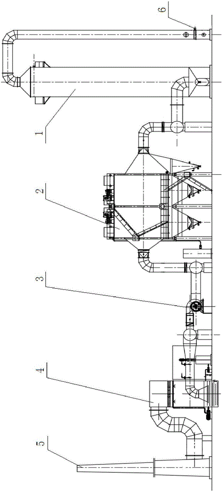
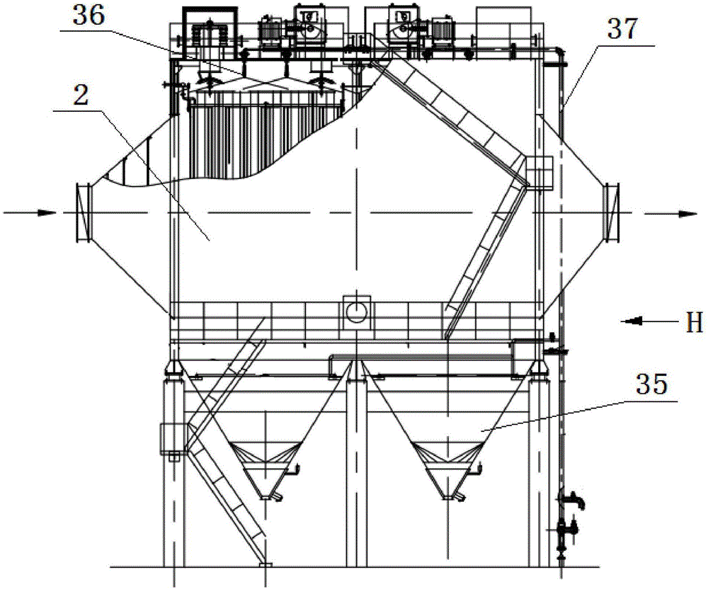
[0050] See Figure 1-Figure 2 , a carbon anode roasting flue gas purification ultra-low emission system, including a spray cooler 1, an electric tar catcher 2, a desulfurization and defluorination device 4, and the flue gas output end of the spray cooler 1 is connected to the electric tar catcher 2 The flue gas inlet of the electric tar catcher 2 is connected to the flue gas inlet of the desulfurization and defluorination device 4 through the exhaust fan 3, and the flue gas outlet of the desulfurization and defluorination device 4 is connected to the chimney 5; the electric tar catcher 2 The anode system in the system adopts a combined multi-functional bimodal plate anode row, and the cathode system adopts prismatic lines and square lines; a hot water cleaning device is installed on the electric tar catcher 2 .

[0051] See image 3 , Figure 4 , Figure...


PUM


Abstract

The invention discloses a carbon anode roasting fume purification ultra-low emission system and process. The carbon anode roasting fume purification ultra-low emission system comprises a spraying cooler, an electrical tar precipitator and a desulfuration defluorination device, wherein the fume output end of the spraying cooler is connected with the fume inlet of the electrical tar precipitator; the fume outlet of the electrical tar precipitator is connected with the fume inlet of the desulfuration defluorination device through an exhaust fan; an anode system in the electrical tar precipitator consists of combined multifunctional double-peak plate type anode rows; a cathode system consists of a ridge wire and a square wire; a hot water cleaning device is arranged on the electrical tar precipitator. By adopting the carbon anode roasting fume purification ultra-low emission system, various pollutant emission indexes can all meet national atmosphere pollutant emission requirements of 2016 to 2030. A high fume purification effect can be achieved. As temperature monitoring points are arranged at key points of the system, possible ignition points can be monitored and controlled, and production security can be ensured. Due to the adoption of the hot water cleaning device, the smoldering phenomenon in the electrical tar precipitator can be effectively prevented. Due to a hybrid polar matching mode, the purification efficiency can be improved.

Description

technical field [0001] The invention relates to the field of carbon anode roasting flue gas treatment in the aluminum industry, in particular to an ultra-low emission system and process for purifying carbon anode roasting flue gas. Background technique [0002] Carbon anode roasting flue gas treatment in the aluminum industry, the roasting flue gas contains asphalt, tar, particulate matter dust, SO 2 , fluoride (solid fluorine), nitride, and a wide variety of carbon products required for electrolytic furnaces in the aluminum industry. During the roasting process, a large amount of asphalt fume (including tar) and particulate dust and sulfur dioxide, fluorine (solid ), HF, nitrogen oxides, and asphalt smoke also contains more than 80 kinds of polycyclic aromatic hydrocarbons such as tritetrabenzopyrcarbazole, and most of them are strong carcinogens with a particle size between 0.1 and 1.0 μm. The largest is about 0.01 μm, and the largest is 1.0 μm. It is difficult to treat, ...

Claims


Application Information

Patent Timeline
IPC IPC(8): B01D50/00B01D53/78B01D53/50B01D53/68
CPCB01D50/00B01D53/507B01D53/68B01D53/78B01D2251/604B01D2251/402B01D2258/0283B01D2257/2027
Inventor 高国纯孟凡斌杨士博
Owner 高国纯
Learn More