
Over-temperature detection system of belt conveyor roller and control method of over-temperature detection system

A belt conveyor and detection system technology, applied in conveyor control devices, conveyors, conveyor objects, etc., can solve problems such as poor working environment, fire, and elevated temperature of idlers, and avoid fire hazards and reuse. High efficiency and simple structure

Inactive Publication Date: 2017-05-31
河北省机电一体化中试基地有限公司
View PDF10 Cites 2 Cited by
  • Summary
  • Abstract
  • Description
  • Claims
  • Application Information

AI Technical Summary

Problems solved by technology

[0004] Belt conveyors usually use rollers to support the belt. The working environment of the conveyor is usually poor. Dust and other debris are easy to enter the bearings of the rollers. The bearing is damaged and the rollers are stuck. The belt continues to rub on the surface of the rollers, making the rollers The temperature keeps rising, which can easily lead to fire, explosion and other accidents

Method used


Image

  • Over-temperature detection system of belt conveyor roller and control method of over-temperature detection system
  • Over-temperature detection system of belt conveyor roller and control method of over-temperature detection system
  • Over-temperature detection system of belt conveyor roller and control method of over-temperature detection system

Examples


Embodiment Construction

[0039] Specific embodiments of the present invention will be described in detail below with reference to the accompanying drawings.

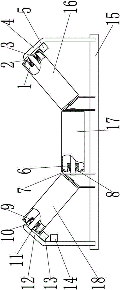
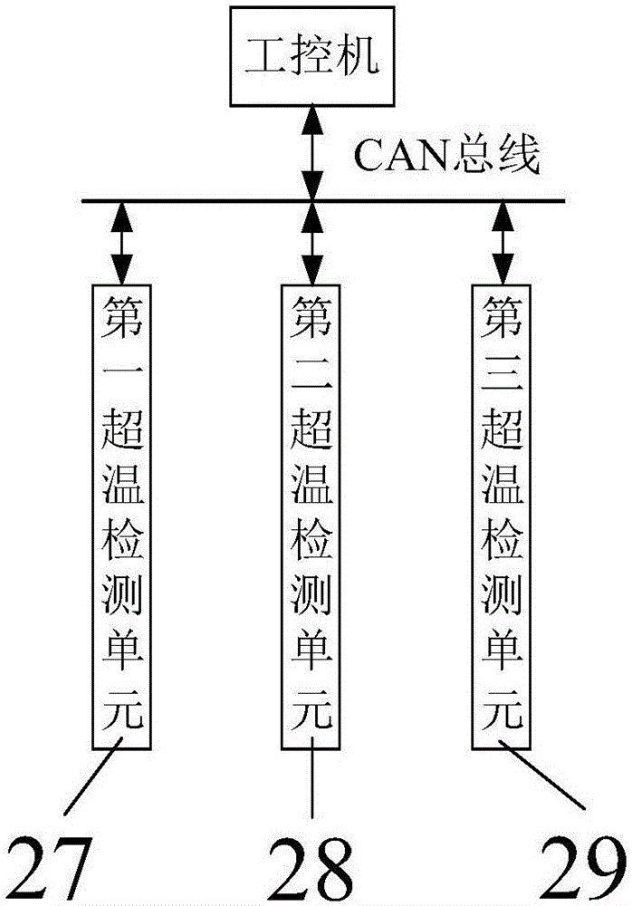
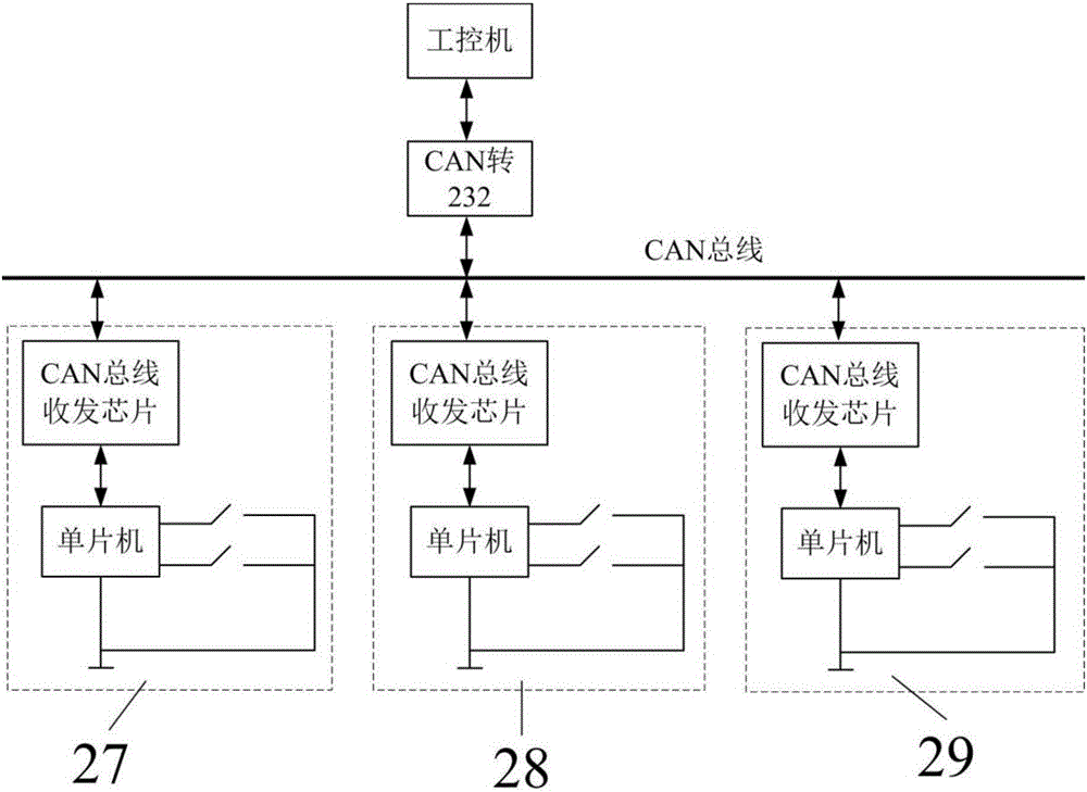
[0040] see Figure 1 to Figure 6 .

[0041] Explanation of symbols in the figure:

[0042] The first bearing 1, the first over-temperature switch 2, the second over-temperature switch 3, the first bracket 4, the first ceramic box 5, the second bearing 6, the third over-temperature switch 7, the fourth over-temperature switch 8, the first Three bearings 9, fifth over-temperature switch 10, sixth over-temperature switch 11, second bracket 12, second ceramic box 13, third ceramic box 14, base 15, idler group, first idler 16, second Idler roller 17, third idler roller 18, outer ring 19, steel ball 20, inner ring 21, copper sheet 22, copper top cover 23, two-way memory alloy spring 24, copper bottom plate 25, cylindrical outer cover 26, the first An over-temperature detection unit 27 , a second over-temperature detection unit 28 , and a third over...


PUM


Abstract

The invention discloses an over-temperature detection system of a belt conveyor roller and a control method of the over-temperature detection system, relating to the technical field of conveying machine measurement and control. According to the over-temperature detection system of the belt conveyor roller, fire is prevented by detecting the temperature of a roller bearing and executing a protection instruction. The over-temperature detection system comprises a roller group, an over-temperature detection unit and an industrial personal computer; the roller group comprises a plurality of rollers and a bracket; the over-temperature detection unit is in communication with the industrial personal computer through a CAN bus and comprises an over-temperature switch, a single chip microcomputer and a CAN bus transceiver chip; and the over-temperature switch is pasted to the roller bearing. Deformation is generated through a two-way shape memory alloy spring at a specific temperature and on-off of a circuit is achieved; and the single chip microcomputer and the CAN bus transceiver chip are packaged in a ceramic box and are arranged on the bracket of a support roller. According to the over-temperature detection system, the automatic detection of over-temperature of the belt conveyor roller is achieved, the over-temperature detection system is stable to operate, low in cost and suitable for massive application, and a fire hazard is completely eradicated effectively.

Description

technical field [0001] The invention relates to an overtemperature detection system and a control method thereof for a belt conveyor idler roller, and belongs to the technical field of automatic control of conveying machinery. Background technique [0002] As the most important conveying equipment for bulk materials, conveying machinery is widely used in ports, railways, grain, coal, chemical industry and other industries. The application is changing to multi-level conveying, spatial three-dimensional cross conveying system, and integrated application of various conveying equipment. With the diversification of conveying system functions and the improvement of equipment complexity, the reliability requirements for each equipment of the conveying system and the overall conveying line are increasing. high. [0003] The conveying machinery industry belongs to the traditional equipment manufacturing industry. There are many domestic conveying machinery manufacturers, but most of...

Claims


Application Information

Patent Timeline
IPC IPC(8): B65G39/12B65G43/02
CPCB65G39/12B65G43/02B65G2203/0266
Inventor 靳晔邓菲王勇庞增拴刘申刘占阳
Owner 河北省机电一体化中试基地有限公司
Learn More