Preparation method and device of spin optical fiber

A technology for rotating optical fibers and optical fiber preforms, which is applied in glass manufacturing equipment, manufacturing tools, etc., can solve the problems of reducing the dispersion of optical fiber polarizing films, making it difficult to maintain a stable wire diameter, and difficult to control, so as to achieve reduced production difficulty, small jitter, Reduce the effect of tower break

Inactive Publication Date: 2017-05-31
YANGTZE OPTICAL FIBRE & CABLE CO LTD
View PDF6 Cites 9 Cited by
  • Summary
  • Abstract
  • Description
  • Claims
  • Application Information

AI Technical Summary

Problems solved by technology

[0004] The preparation method of the traditional low birefringence optical fiber is proposed in the patent "Manufacturing method of low polarization mode dispersion single-mode optical fiber and optical fiber prepared by the method" with the publication number of 1472153. This method is not suitable for optical fibers that rotate at a uniform speed in a single direction of rotation. This method is mainly to reduce the dispersion of the polarization film of the optical fiber, rather than to produce spun optical fibers
The preparation method of the spun optical fiber is proposed in the patent "Manufacturing method of twisted optical fiber" with the publication number of 103359929A. The preform is used to draw a large core diameter optical fiber and then reheated and rotated to form a twisted optical fiber. This method requires the large core diameter optical fiber The coating layer is peeled off and then drawn and twisted. This method is more complicated and is not suitable for manufacturing circular polarization maintaining optical fibers in commercial production. In addition, the second drawing of this method uses horizontal drawing, which will affect the geometry and shape of the optical fiber under the action of gravity. structural impact
The Chinese patent "A Manufacturing Method of Rotating Optical Fiber and Rotating Fiber Collection Device" with the patent number of 102503116 proposes to use the method of rotating the take-up reel to prepare the rotating optical fiber. This method is difficult to control and it is difficult to maintain the stability of the wire diameter.

Method used


Image

  • Preparation method and device of spin optical fiber
  • Preparation method and device of spin optical fiber

Examples


Embodiment Construction

[0035] In order to make the object, technical solution and advantages of the present invention clearer, the present invention will be further described in detail below in conjunction with the accompanying drawings and embodiments. It should be understood that the specific embodiments described here are only used to explain the present invention, not to limit the present invention.

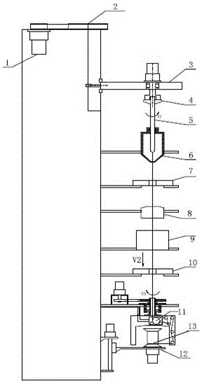
[0036] figure 1It is the preparation equipment of the spun optical fiber of the present invention. It includes rotating drawing, vertical driving device 1, feeding mechanism 2, rotating device 3, clamping rod mechanism 4, heating furnace 6, first wire diameter measuring instrument 7, coating device 8, curing device 9, second wire diameter Measuring instrument 10, traction device 11, take-up device 12. The height of the drawing tower body is 5-6m, and the threaded holes are distributed on the tower body, and the equipment is installed on the tower body from top to bottom; Fast feeding; rod clampi...


PUM

PropertyMeasurementUnit
distanceaaaaaaaaaa
diameteraaaaaaaaaa
warpageaaaaaaaaaa

Abstract

The invention discloses a preparation method and device of spin optical fiber. The preparation method comprises the steps of clamping an optical fiber preformed rod tightly on a rod clamping mechanism of a fiber-drawing tower, moving the optical fiber preformed rod to a hot area of a heating furnace by a feed mechanism, heating the optical fiber perform rod to a molten condition and then forming optical fiber, wherein the optical fiber is continuously cooled when being pulled down, and the spin character can be fixed; enabling the optical fiber to pass through a coating device and performing solidification, and finally, pulling continuously by a pulling device at a speed of V2 and collecting to a wire take-up device; when the diameter of the optical fiber reaches a required amount and tends to be stable, the rod clamping mechanism spins at an angular speed of V1, a main pulling mechanism spins at an angular speed of V3, and meets the requirement that V2 / (V1 plus V3) equals to mu, wherein mu is a screw pitch of the prepared spin optical fiber. In the preparation method provided by the invention, the spin optical fiber is prepared by the preformed rod and the pulling device through performing wire-drawing in reverse rotation at the same time, which is simpler and more reliable than a preparation method of heating, melting, stretching and rotating after peeling a coating layer from optical fiber of a finished product.

Description

technical field [0001] The invention belongs to the technical field of optical fiber and cable, and more specifically relates to a preparation method and equipment for spinning optical fibers. Background technique [0002] In recent years, with the wide application of fiber optic current transformers, spun fiber has been paid more attention by fiber optic manufacturers. The working principle of the fiber optic current transformer is the commonly used Faraday magneto-optic effect. When a beam of linearly polarized light passes through a magneto-optical material placed in a magnetic field, the polarization plane of the linearly polarized light will rotate linearly with the magnitude of the magnetic field parallel to the direction of the light. By measuring the rotation angle of the plane of polarization of linearly polarized light around a current-carrying conductor, the current value in the conductor can be measured indirectly. [0003] A typical fiber optic current transfo...

Claims


Application Information

Patent Timeline
Patent Type & Authority Applications(China)
IPC IPC(8): C03B37/025C03B37/029C03B37/03
Inventor 黄开放程治民张心贲卢松涛何勤国乐正舒健毛德润彭慎叶心屏
Owner YANGTZE OPTICAL FIBRE & CABLE CO LTD
Why Eureka
Try Eureka