

Electrostatic spinning device with porous nozzle
A technology of electrospinning and nozzles, which is applied in textile and papermaking, filament/thread forming, fiber processing, etc. Effect
- Summary
- Abstract
- Description
- Claims
- Application Information
AI Technical Summary
Problems solved by technology
Method used
Image

Examples
Embodiment 1
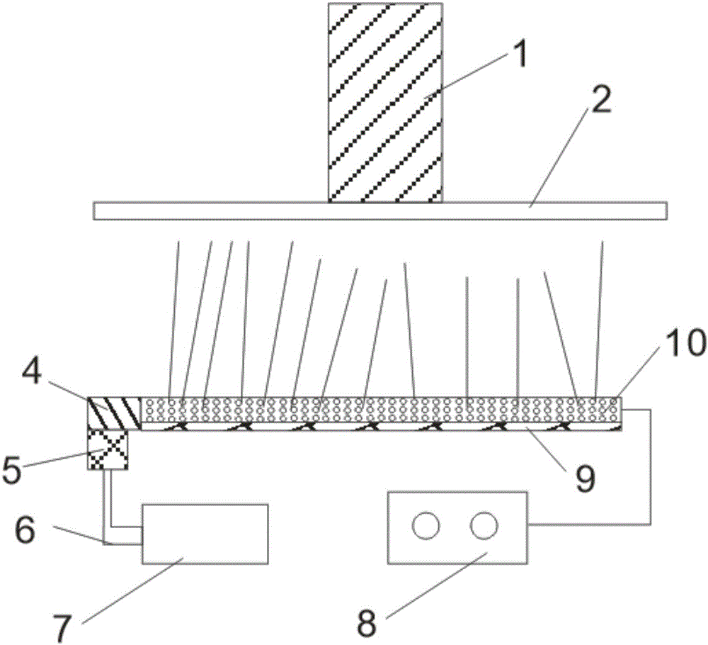
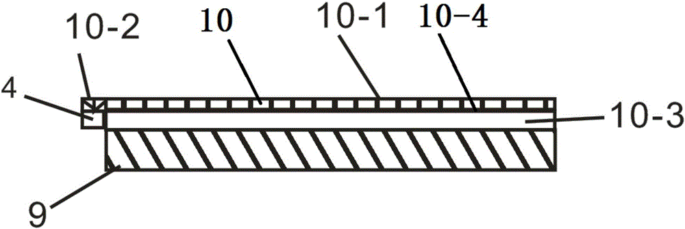
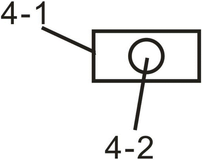
[0031] refer to Figure 1-Figure 4 , the electrospinning device with the porous nozzle of the present embodiment comprises the spinning receiving plate 2 for receiving the nanofiber, the porous nozzle spinneret for ejecting the nanofiber, the spinning solution storage for storing the spinning solution. A liquid container 7, a pressure pump 5 for delivering the spinning liquid to the spinneret of the multi-hole nozzle, and a high-voltage generator 8 for providing high-voltage static electricity for the spinneret of the multi-hole nozzle. Described porous nozzle spinneret comprises the spinneret container 10 that is made of insulating material, and the top of spinneret container 10 is provided with a plurality of spinneret holes that communicate with the inner chamber 10-3 of spinneret container 10, and each spinneret Metal nozzles 10-1 are arranged in the hole, and all metal nozzles 10-1 are connected to each other and connected to the high-pressure generator 8; both ends of th...
Embodiment 2
[0042] see Figure 5-Figure 6 , The difference between this embodiment and Embodiment 1 is that in this embodiment, the fiber collection unit is a circular collection mechanism, which consists of two transmission rollers 3 and surrounding the transmission roller 3 The loop collection belt 11 constitutes.
[0043] The spinning container 10 is a cylindrical container.
Embodiment 3
[0045] see Figure 7 and Figure 8 , The difference between this embodiment and Embodiment 1 is that in this embodiment, the fiber collection unit is a one-way transmission and collection mechanism, and the one-way transmission and collection mechanism is composed of a driving roller 3 and a spinning receiving plate 2 The one-way collection belt 12 that conveys in one direction below constitutes.
[0046] The spinning container 10 is a square container, and the spinning hole is a triangular hole.
PUM
 Abstract
Description
Claims
Application Information