Composite steel plate and manufacturing method thereof

A technology of composite steel plate and steel plate, applied in the direction of building materials, etc., can solve the problem of not being able to fundamentally solve the problem of bearing capacity of steel beams, the impact of carbon fiber cloth reinforcement on the durability of steel structures, and the inability to greatly improve the bearing capacity of steel beams, etc. Achieving good corrosion resistance, light weight and light weight

Active Publication Date: 2019-12-13
CHINA UNIV OF MINING & TECH +1
View PDF1 Cites 0 Cited by
  • Summary
  • Abstract
  • Description
  • Claims
  • Application Information

AI Technical Summary

Problems solved by technology

However, the use of adhesives to bond carbon fiber cloth, plates and steel components will have the following defects: (1) The thermal expansion coefficient of steel is relatively different from that of carbon fiber cloth. After the reinforcement is completed, there will inevitably be residual thermal stress. Unfavorable reinforcement effect
(2) At present, there is no special binder for carbon fiber cloth reinforced steel structures, and the use of different binders will inevitably cause differences in reinforcement performance, which is not conducive to design calculations
(3) Different adhesives have different sensitivity to environmental factors such as temperature, humidity, and ultraviolet rays. Under the influence of such factors, the bond strength will be reduced, which will inevitably affect the durability of carbon fiber cloth reinforced steel structures.
However, this method cannot greatly improve the bearing capacity of the steel beam, and cannot fundamentally solve the bearing capacity problem of the steel beam.
Apart from this, this method also does not improve the fatigue properties of the steel beams and does not help the corrosion resistance of the steel beams

Method used


Image

  • Composite steel plate and manufacturing method thereof
  • Composite steel plate and manufacturing method thereof
  • Composite steel plate and manufacturing method thereof

Examples


Embodiment Construction

[0028] The present invention will be described in detail below in conjunction with the accompanying drawings.

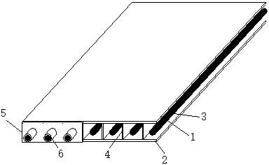
[0029] Such as figure 1 As shown, the composite steel plate of the present invention includes a sandwich steel plate, fiber tendons 3, anchors 6, backing plate 5; the sandwich steel plate includes an upper panel 1 and a lower panel 2, and the equidistant distance The web 4 is arranged; the fiber reinforcement 3 passes through the sandwich steel plate, and the two ends are fixed by the anchor 6 and the backing plate 5; this embodiment adopts carbon fiber reinforcement, and the carbon fiber reinforcement is divided into two types: ribbed and non-ribbed, with a diameter of ≥ 3mm , the present embodiment uses a carbon fiber bar with a diameter of 3mm; the sandwich steel plate adopts a 3mm thick stainless steel plate, and the anchorage 6 is a tapered anchorage.

[0030] The method for making composite steel plate provided by the invention comprises the following steps: ...


PUM

PropertyMeasurementUnit
diameteraaaaaaaaaa
diameteraaaaaaaaaa

Abstract

The invention discloses a composite steel plate and a manufacturing method thereof. The composite steel plate comprises a sandwiched steel plate, fiber bars or bundles, anchors and backing plates, wherein the sandwiched steel plate comprises an upper panel and a lower panel, webs are arranged between the upper panel and the lower panel at equal intervals, the fiber bars or bundles penetrate through the sandwiched steel plate, and the two ends are fixed by the anchors and the backing plates. The composite steel plate is light in weight, thin, large in bearing force, high in anti-fatigue performance, easy to construct and capable of improving the working performance of reinforced steel beams. The fiber bars or bundles used in the composite steel plate are small in diameter, and the thickness of the composite steel plate can be greatly reduced. The hollow stainless steel plate and the fiber bars or bundles are high in corrosion resistance, and the composite material composed of the two materials has weldability and can be used for strengthening and reinforcing the steel beams.

Description

technical field [0001] The invention relates to a composite steel plate and a manufacturing method thereof, in particular to a composite steel plate for bending resistance reinforcement of steel beams and a manufacturing method thereof. Background technique [0002] Fiber products such as carbon fiber cloth and board have high strength, low density, thin thickness, and excellent work performance. At present, they are widely used in the reinforcement and reinforcement of reinforced concrete structures such as shear resistance, bending resistance, and earthquake resistance, and can limit concrete cracking. Improve the distribution of cracks. It can be used to strengthen the steel structure, which can significantly improve the bearing capacity of the steel structure and improve the fatigue performance of the steel components. [0003] At present, fiber products such as carbon fiber cloth to strengthen concrete structures or steel structures are bonded to the structure through ...

Claims


Application Information

Patent Timeline
Patent Type & Authority Patents(China)
IPC IPC(8): E04C2/26
CPCE04C2/26
Inventor 盛杰夏军武
Owner CHINA UNIV OF MINING & TECH
Why Eureka
Try Eureka