A device and method for increasing mechanical power
A technology of mechanical power and engine, applied in the direction of mechanical equipment, charging system, engine components, etc., can solve the problems of increasing construction cost, high cost, impact on construction and installation, etc. Effect
- Summary
- Abstract
- Description
- Claims
- Application Information
AI Technical Summary
Problems solved by technology
Method used
Image
Examples
Embodiment 1
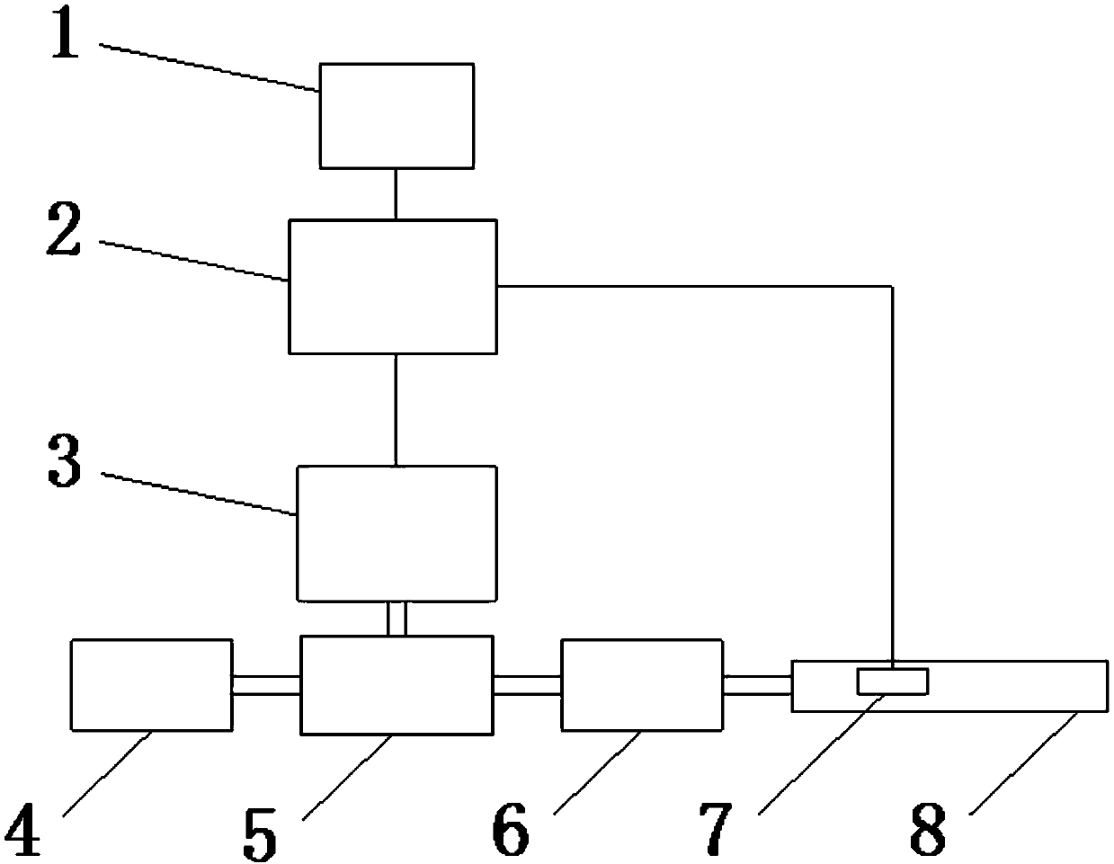
[0029] Embodiment 1: a kind of portable turbocharging system, such as figure 1 with Figure 4 As shown, it includes: an exhaust pipe 8 connected to the exhaust end of the engine 6, a flow sensor 7 is arranged in the exhaust pipe 8, and the flow sensor 7 transmits the exhaust gas flow signal to the control system 2, and the control system 2 is powered by the vehicle power supply 1 to control System 2 controls the rotation of booster motor 3, and the output shaft of booster motor 3 drives turbine 5 to rotate. The gas outlet is airtightly connected with the intake port of the engine 6 .
[0030] The control system 2 is a PLC control system.
[0031] The air filter 4 includes a housing 4-1, the housing 4-1 has an air inlet 4-6, the arc portion 4-2 is below the baffle plate 1, and the inside of the housing 1 is provided with a deflector 4-6. 5 and filter paper 4-4; wherein, the filter paper 4-4 is not in contact with the bottom of the housing 4-1.
[0032] In this embodiment, t...
Embodiment 2
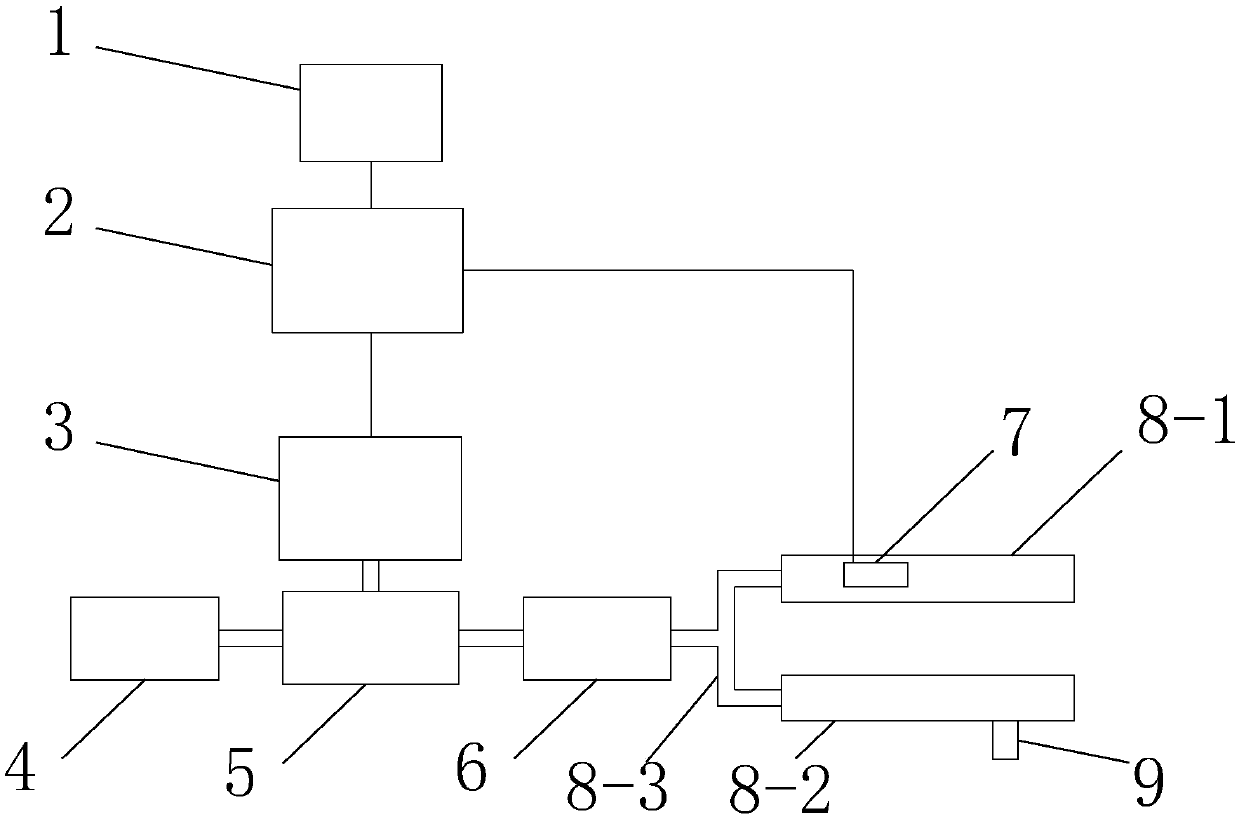
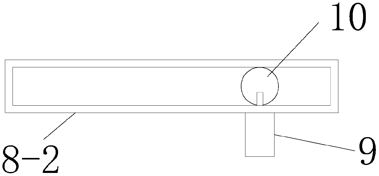
[0039] Embodiment 2: a kind of portable turbocharging system, such as Figure 2-4 As shown, it includes: an exhaust pipe 8 connected to the exhaust end of the engine 6; the exhaust pipe 8 includes a shunt pipe 8-3, the left side of the shunt pipe 8-3 is connected to the exhaust end of the engine 6, and the right side is respectively connected to the first exhaust gas The pipe 8-1 is connected to the second waste gas pipe 8-2, and the first waste gas pipe 8-1 has a flow sensor therein. The second waste gas pipe 8-2 is provided with a back pressure motor 9, the main shaft of the power back motor 9 drives the back pressure plate 10 to rotate, and the back pressure plate 10 is located inside the second waste gas pipe 8-2.
[0040] The exhaust pipe 8 is provided with a flow sensor 7, the flow sensor 7 transmits the exhaust gas flow signal to the control system 2, the control system 2 controls the rotation of the booster motor 3, the output shaft of the booster motor 3 drives the tu...
PUM
 Abstract
Description
Claims
Application Information
 - R&D
- Intellectual Property
- Life Sciences
- Materials
- Tech Scout
- Unparalleled Data Quality
- Higher Quality Content
- 60% Fewer Hallucinations
Browse by: Latest US Patents, China's latest patents, Technical Efficacy Thesaurus, Application Domain, Technology Topic, Popular Technical Reports.
© 2025 PatSnap. All rights reserved.Legal|Privacy policy|Modern Slavery Act Transparency Statement|Sitemap|About US| Contact US: help@patsnap.com


