Pilot hydraulic control system based on multi-shuttle-valve set and drilling machine

A hydraulic control system and pilot control valve technology, applied in the field of hydraulic machinery, can solve the problems of large space occupation, many assembly pipelines, and difficult processing, and achieve the effects of reducing hydraulic connections, reliable idle speed control, and easy processing

Active Publication Date: 2017-05-31
CHTC JOVE HEAVY IND
View PDF8 Cites 4 Cited by
  • Summary
  • Abstract
  • Description
  • Claims
  • Application Information

AI Technical Summary

Problems solved by technology

[0006] The main purpose of the present invention is to provide a pilot hydraulic control system based on a multi-connected shuttle valve group, aiming to solve the problems of the existing multi-connected shuttle valve group with complex structure, large space occupation, many assembly pipelines and difficult processing

Method used


Image

  • Pilot hydraulic control system based on multi-shuttle-valve set and drilling machine
  • Pilot hydraulic control system based on multi-shuttle-valve set and drilling machine
  • Pilot hydraulic control system based on multi-shuttle-valve set and drilling machine

Examples


Embodiment 1

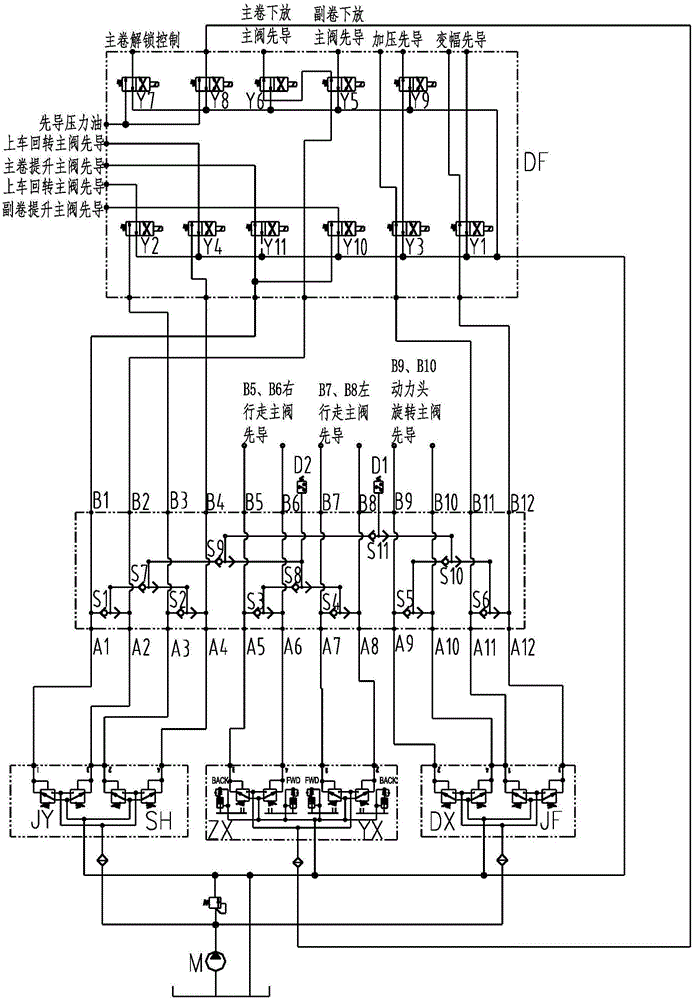
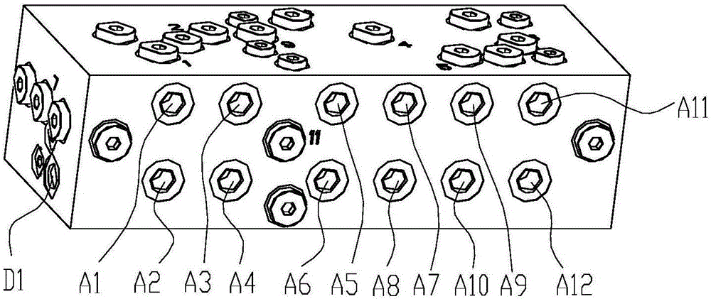
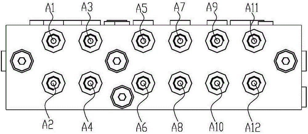
[0054] figure 1 It is a principle diagram of the pilot hydraulic control system using eleven shuttle valve groups in the pilot hydraulic control system based on multiple shuttle valve groups proposed in Embodiment 1 of the present invention. figure 2 for figure 1 Schematic diagram of the three-dimensional structure of the eleven-connected shuttle valve group. image 3 for figure 2 main view. Figure 4 for figure 2 back view. Figure 5 for figure 2 left view of .

[0055] see Figure 1 to Figure 5 , the pilot hydraulic control system based on the multi-connected shuttle valve group includes the hydraulic pump M connected to the oil tank, the winch pilot control valve JY connected to the hydraulic pump, the turning pilot control valve SH of the boarding car, the pilot control valve DX of the power head rotation, and the Pressure variable amplitude pilot control valve JF, left travel pilot control valve ZX, right travel pilot control valve YX, eleven-connected shuttle...

Embodiment 2

[0062] Figure 6 It is a schematic diagram of the pilot hydraulic control system using five shuttle valve groups in the pilot hydraulic control system based on multiple shuttle valve groups proposed in Embodiment 2 of the present invention. Figure 7 for Figure 6 The front view of the five-way shuttle valve group. Figure 8 for Figure 6 back view. Figure 9 for Figure 6 left view of . Figure 10 for Figure 6 right view of .

[0063] see Figure 6 to Figure 10 The difference between the second embodiment and the first embodiment lies in that: the boarding rotary pilot control valve SH, the left travel pilot control valve ZX, and the right travel pilot control valve YX are directly connected to the solenoid valve group DF.

[0064] The second embodiment differs from the first embodiment in that: the multi-connected shuttle valve group is a five-connected shuttle valve group.

[0065] The five-connected shuttle valve group includes a first oil inlet A1', a second oil...


PUM


Abstract

The invention discloses a pilot hydraulic control system based on a multi-shuttle-valve set. The pilot hydraulic control system comprises a hydraulic pump connected with an oil tank, a pilot control valve set connected with the hydraulic pump, the multi-shuttle-valve set and a solenoid valve set composed of multiple solenoid directional valves. The pilot control valve set comprises a winch pilot control valve, a loading rotary pilot control valve, a power head rotating pilot control valve, a pressurization variable-amplitude pilot control valve, a left walking pilot control valve and a right walking pilot control valve. The multi-shuttle-valve set comprises multiple shuttle valves arranged in a valve body and common oil outlets arranged on one side of the valve body, each shuttle valve comprises two inlets and a working opening, the working opening of each shuttle valve communicates with one corresponding common oil outlet, and each common oil outlet is an idling-speed pressure signal collection opening. According to the pilot hydraulic control system, the multi-shuttle-valve set is adopted for acquiring idling-speed pressure signals, and idling speed control is reliable; and the appearance of the multi-shuttle-valve set is reduced, oil passing hole channels in the multi-shuttle-valve set are reduced, and machining is easier.

Description

technical field [0001] The invention belongs to the technical field of hydraulic machinery, and in particular relates to a pilot hydraulic control system based on a multi-connected shuttle valve group and a drilling rig. Background technique [0002] For hydraulic construction machinery such as drilling rigs, in order to comprehensively consider the comfort of the operator’s operation, avoid the harmfulness of frequent engine starts and equipment energy saving and other comprehensive factors, the engine idle speed control method is designed in combination with hydraulic pressure and electrical control-if the equipment is within the set time When there is no work, the electrical control issues instructions to reduce the engine speed to different levels of idle speed according to the length of idle time. The usual situation is to start the transmitter, but it cannot work immediately, and it is not appropriate to stop it. Such a situation occurs frequently. [0003] The shuttl...

Claims


Application Information

Patent Timeline
Patent Type & Authority Applications(China)
IPC IPC(8): F15B13/02
CPCF15B13/02F15B2013/002F15B2013/006
Inventor 马少焱吴江苏
Owner CHTC JOVE HEAVY IND
Why Eureka
Try Eureka