Gas-fired boiler flue gas latent heat recycling system

A gas-fired boiler and flue gas technology, which is applied in preheating, feed water heaters, lighting and heating equipment, etc., can solve the problems of high cost of heat pump and operation, large heat exchange area of ​​heat exchanger, and unable to reduce the exhaust gas temperature. , to save fuel, reduce the heat exchange area, and facilitate the recovery of latent heat

Active Publication Date: 2017-05-31
INST OF ENGINEERING THERMOPHYSICS - CHINESE ACAD OF SCI
View PDF5 Cites 13 Cited by
  • Summary
  • Abstract
  • Description
  • Claims
  • Application Information

AI Technical Summary

Problems solved by technology

The conventional latent heat recovery method is to use feed water and wet flue gas to exchange heat through a partition wall heat exchanger to reduce the exhaust gas temperature. This method has been widely used, but its disadvantages are that the heat exchange area of ​​the heat exchanger is large, In addition, the heat exchanger needs to withstand the corrosiveness of the flue gas condensate, and the cost is high; on the other hand, the maximum heat recovery is limited by the feed water temperature, and the exhaust gas temperature cannot be lowered below the feed water temperature. When the feed water temperature is high , the latent heat recovery rate is low
Aiming at the problem of high feed water temperature and low heat recovery rate, people have developed a method of combining latent heat recovery of flue gas with absorption or compression heat pump. The disadvantage of this method is that the cost of the heat pump and the operation are relatively high.

Method used


Image

  • Gas-fired boiler flue gas latent heat recycling system

Examples


Embodiment Construction

[0025] In order to make the object, technical solution and advantages of the present invention clearer, the present invention will be described in further detail below in conjunction with specific embodiments and with reference to the accompanying drawings.

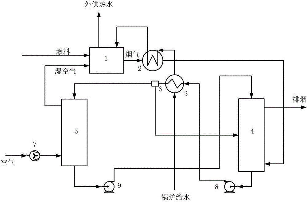
[0026] By recycling the latent heat of the flue gas to heat and humidify the air, the dew point temperature of the flue gas can be increased, so that a large amount of latent heat of the flue gas can be recovered even when the return water temperature is high, but there is a heat exchanger for recovering the latent heat of the flue gas The problem of small temperature difference and large heat transfer load, and the current heat exchanger that uses an indirect contact heat exchanger to recover the latent heat of flue gas has a large heat transfer area and the risk of low-temperature acid corrosion. On the basis of in-depth research on the heat absorption and release process of air humidification and latent heat recovery, t...


PUM


Abstract

The invention provides a gas-fired boiler flue gas latent heat recycling system. Flue gas of a gas-fired boiler body enters a flue gas / circulating water contact tower, the flue gas in the flue gas / circulating water contact tower and circulating water in a circulating water subsystem make direct countercurrent contact for heat exchange, gas-fired boiler flue gas latent heat recycling is achieved, the high-temperature part of latent heat recycled from the flue gas is used for heating boiler feed water, and the low-temperature part of the latent heat is used for heating and humidifying combustion air and fuel gas, so that emission of combustion NOx is reduced. According to the gas-fired boiler flue gas latent heat recycling system, the flue gas and the circulating water make direct contact for heat exchange in the flue gas / circulating water contact tower, the heat exchange area is greatly decreased, the cost is reduced, and meanwhile the acid corrosion problem of a heat exchanger is avoided; by adopting a multi-segment heat exchange mode, the purpose that multiple segments of towers make direct contact with one another for heat exchange on the basis of different water-gas ratios is achieved, therefore, heat release of the flue gas latent heat and heat absorption of the circulating water are matched with each other and combined with air and fuel heating and humidifying, the flue gas latent heat recycling rate is significantly increased, and the flue gas latent heat can be recycled to the maximum extent.

Description

technical field [0001] The invention relates to recovery and utilization of flue gas low-temperature waste heat and NO x The technical field of emission reduction, in particular, a gas boiler flue gas latent heat recovery and utilization system. Background technique [0002] my country has a large number of boilers that burn gas (natural gas, etc.), liquid and other hydrocarbon fuels to generate hot water / steam, providing heat for industry and life. The flue gas of hydrocarbon fuel combustion contains a large amount of water vapor, which is discharged with the flue gas, causing a large amount of energy and water loss. The flue gas burned by gas-fired boilers contains a large amount of water vapor, and the water vapor will release a large amount of latent heat during the condensation process. For example, the dew point temperature of the flue gas from pure methane combustion is close to 60°C, that is, starting from about 60°C, the flue gas continues to cool down, then The w...

Claims


Application Information

Patent Timeline
Patent Type & Authority Applications(China)
IPC IPC(8): F22D1/36
CPCF22D1/36
Inventor 肖云汉王波路源张哲巅赵丽凤
Owner INST OF ENGINEERING THERMOPHYSICS - CHINESE ACAD OF SCI
Why Eureka
Try Eureka