Solid energy storage module and electric heating solid energy storage device

An energy storage module and energy storage device technology, applied in electric heating devices, heat storage equipment, ohmic resistance heating, etc., can solve the problems of complex structure, short life of electric heating tubes, troublesome maintenance and replacement, etc.

Inactive Publication Date: 2017-05-31
玉环未涞流体科技有限公司
View PDF10 Cites 4 Cited by
  • Summary
  • Abstract
  • Description
  • Claims
  • Application Information

AI Technical Summary

Problems solved by technology

[0011] However, the above-mentioned technical system has a complex structure, long heat storage and release time, short life of the electric heating tube and high cost, and the electric heating tube is in a dry burning state for a long time, resulting in a short life of the electric heating tube. Trouble, even downtime for maintenance

Method used


Image

  • Solid energy storage module and electric heating solid energy storage device
  • Solid energy storage module and electric heating solid energy storage device
  • Solid energy storage module and electric heating solid energy storage device

Examples


Embodiment 1

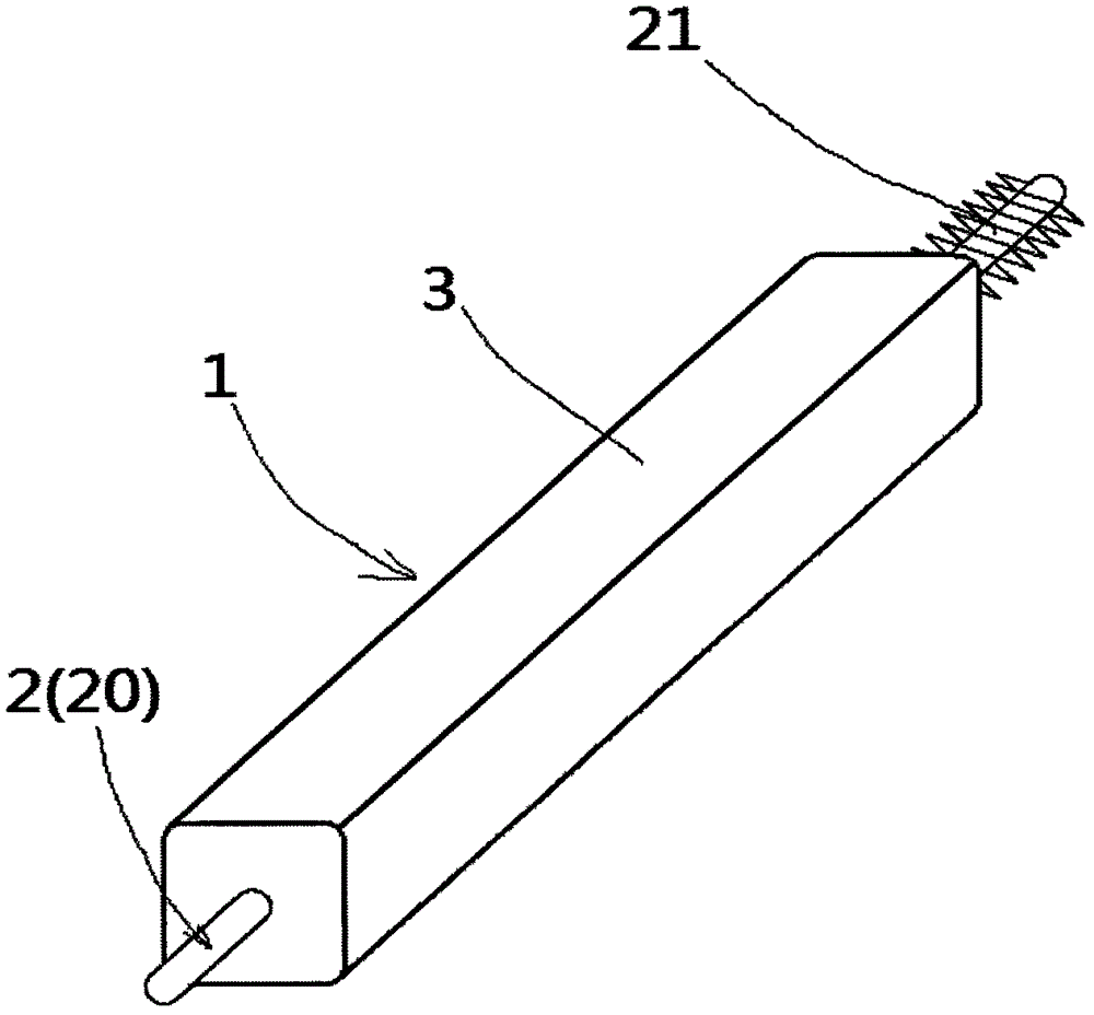
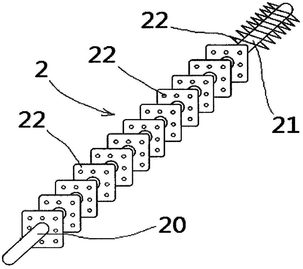
[0052] Such as figure 1 with figure 2 As shown, a solid energy storage module includes a solid energy storage module 1, the solid energy storage module 1 includes a heat pipe 2 and an energy storage material body 3 wrapped outside the heat pipe 2, and the heat pipe 2 runs through the energy storage material body 3, and the heat-absorbing section 20 and the heat-dissipating section 21 at both ends of the heat pipe 2 extend out of the body of the energy storage material body 3, and a number of heat-conducting fins are arranged on the outer surface of the heat pipe 2 except the heat-absorbing section 20 twenty two. The heat conduction fins 22 on the heat dissipation section 21 are different in shape from the heat conduction fins 22 in the energy storage material body 3 , one is an annular heat conduction fin, and the other is a square heat conduction fin with several through holes. The heat pipe used is a special heat pipe. The heat transfer medium inside the heat pipe is made...

Embodiment 2

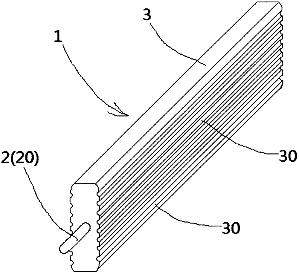
[0069] Such as figure 1 with image 3 As shown, the solid energy storage module 1 includes a heat pipe 2 and an energy storage material body 3 wrapped outside the heat pipe 2. The heat pipe 2 runs through the body of the energy storage material body 3, and only the heat absorbing section 20 extends out of the energy storage material. Outside the body of the body 3, a number of heat conducting fins 22 are arranged on the outer surface of the heat pipe 2 except the heat absorbing section 20, and a number of grooves 30 for air circulation are arranged on the outer surface of the energy storage material body 3. Others are the same as in Embodiment 1, and will not be repeated here.

Embodiment 3

[0071] Such as figure 1 , figure 2 with Figure 4 As shown, an electrothermal solid energy storage device 11 includes the solid energy storage module 1 shown in Embodiment 1, the induction coil 4, the high-frequency current generation and control device 5, the outer heat preservation shell 6, the temperature sensor 7, and several The solid energy storage modules 1 are regularly stacked in the outer heat preservation shell 6, and the heat absorption sections 20 of each solid energy storage module 1 are arranged on the same side, and each heat absorption section 20 is covered with an induction coil 4 , and all the induction coils 4 and the temperature sensors 7 are connected to the high-frequency current generation and control device 5, correspondingly, the heat dissipation section 21 is located on the other side, and forms a heat dissipation zone with the inner side of the outer heat preservation shell 6 Cavity 8, and several air outlets 80 and return air outlets 81 communic...


PUM


Abstract

The invention innovatively provides a novel solid energy storage module and an electric heating solid energy storage device. The serial problems that an existing solid energy storage type electric boiler and a heat exchange structure thereof are complex in system structure, long in heat storage and release time, short in electric heating pipe service life, high in cost, complicated in maintenance and the like will be changed. By means of high heat conductivity of a special heat pipe, a heat absorption segment of the heat pipe is heated through a high-frequency induction coil, by means of heat transfer of multiple heat conduction fins on the heat pipe, a solid energy storage material body wrapping the outer portion of the heat pipe can be fast heated, and energy storage can be achieved; and during heat release, heat energy stored in the solid energy storage material body can be fast guided out. The electric heating solid energy storage device is formed by multiple solid energy storage modules, and can be used in cooperation with a heat exchanger, high-temperature steam or hot water for heating and the like can be generated, and a small domestic energy storage heater can be formed.

Description

technical field [0001] The invention belongs to the technical field of solar heat utilization, and in particular relates to a technology of a solid energy storage module and an electrothermal solid energy storage device. Background technique [0002] According to relevant data and statistics, the fundamental measure to reduce or eliminate smog is to significantly reduce the emission of major pollutants. One of the keys is to speed up the adjustment of energy structure and solve the problem of coal combustion pollution and other pollution emissions. [0003] The design and development of solid energy storage atmospheric pressure electric boilers are aimed at the replacement products of many small and medium-sized coal-fired boilers. Due to their low thermal efficiency, environmental protection and management difficulties, small and medium-sized coal-fired boilers have been widely used in developed countries and cities above medium-sized in my country. It is forbidden to use, a...

Claims


Application Information

Patent Timeline
Patent Type & Authority Applications(China)
IPC IPC(8): F28D20/00F28D15/02F28F21/08H05B6/02
CPCF28D15/0275F28D20/0056F28D2020/0078F28F21/083H05B6/02H05B2206/02Y02E60/14
Inventor 李增清李渊
Owner 玉环未涞流体科技有限公司
Why Eureka
Try Eureka