
Optical element high-precision measuring device based on real-time monitoring movement errors

A technology of motion error and optical components, which is applied in the direction of measuring devices, optical devices, instruments, etc., can solve the problems that cannot meet the requirements of large-caliber optical component contour detection accuracy, etc., achieve convenient uncertainty and error analysis and compensation, and improve detection The effect of precision

Inactive Publication Date: 2017-05-31
HARBIN INST OF TECH
View PDF6 Cites 18 Cited by
  • Summary
  • Abstract
  • Description
  • Claims
  • Application Information

AI Technical Summary

Problems solved by technology

[0003] The purpose of the present invention is to solve the problem that the existing motion error monitoring means cannot meet the requirements for the detection accuracy of the profile of large-diameter optical elements, and to provide a high-precision measurement device for optical elements based on real-time monitoring of motion errors

Method used


Image

  • Optical element high-precision measuring device based on real-time monitoring movement errors

Examples


specific Embodiment approach 1

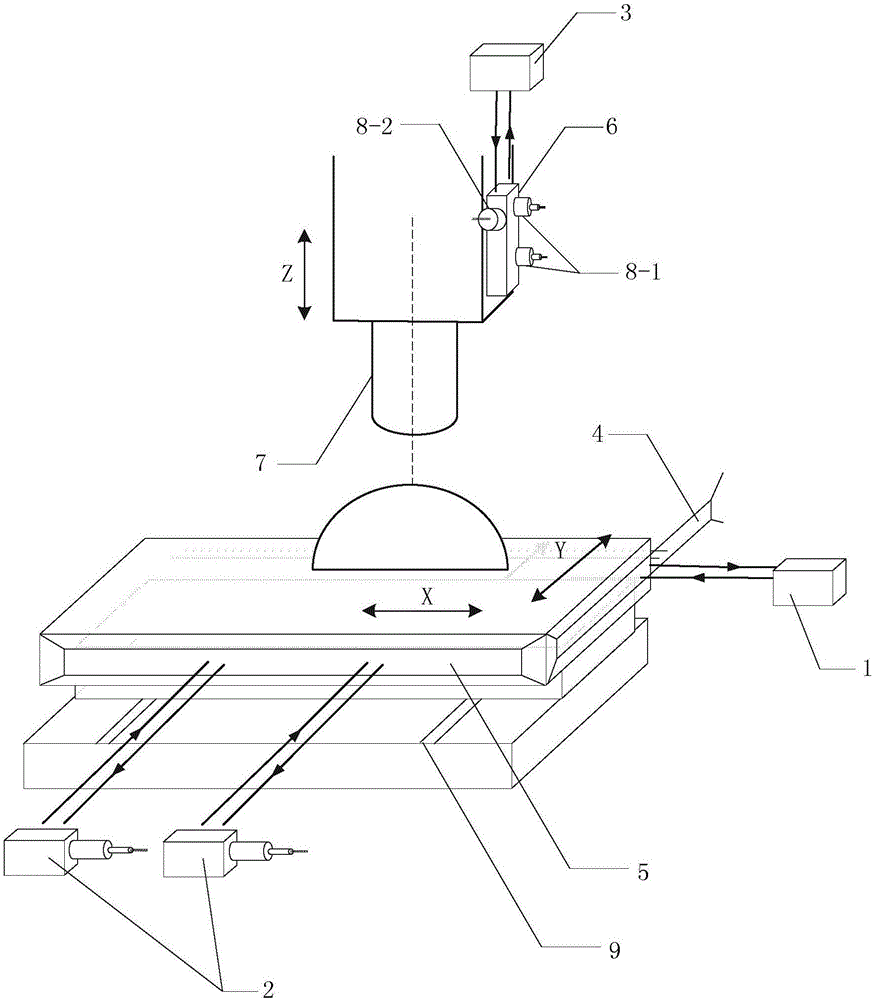
[0014] Specific implementation mode one: the following combination figure 1 Describe this embodiment, the high-precision measurement device for optical components based on real-time monitoring of motion errors described in this embodiment, the measurement device includes a two-dimensional air bearing guide rail 9, a laser interferometer module, a capacitive sensor module and a laser confocal probe 7;

[0015] The laser interferometer module includes X-direction laser interferometer 1, Y-direction dual-path laser interferometer 2, Z-direction confocal probe laser interferometer 3, X-direction reflection flat 4, Y-direction reflection flat 5 and Z-direction reflection flat Crystal 6;

[0016] The capacitive sensor module includes a dual-channel capacitive sensor 8-1 and a capacitive sensor 8-2;

[0017] The large-aperture optical element is placed on the air-floating platform above the two-dimensional air-floating guide rail 9;

[0018] The X-direction laser interferometer 1 i...

specific Embodiment approach 2

[0023] Specific implementation mode two: the following combination figure 1 Describe this embodiment, this embodiment will further explain Embodiment 1, the X-direction laser interferometer 1, the Y-direction dual-path laser interferometer 2 and the Z-direction confocal probe laser interferometer 3 are all dual-frequency laser interferometers, measuring The resolution is 0.6nm.

[0024] In this embodiment, the X-direction laser interferometer 1, the Y-direction two-way laser interferometer 2 and the Z-direction confocal probe laser interferometer 3 can not only monitor the displacement in the XY direction in real time, but also provide real-time information on the movement of the X-direction rail. Angular motion error in the Y direction for later uncertainty analysis and compensation.

specific Embodiment approach 3

[0025] Specific implementation mode three: the following combination figure 1 Describe this embodiment, this embodiment will further explain Embodiment 1 or 2, the Y-direction dual-path laser interferometer 2 determines the existence of the X-direction rail movement by monitoring the displacement difference measured by the two-way laser interferometer during the X-direction rail movement. Angle deflection.

[0026] In this embodiment, when the Y-direction two-way laser interferometer 2 detects that there is an angular deflection in the movement of the X-direction rail, compensation is performed in time.


PUM


Abstract

The invention relates to an optical element high-precision measuring device based on real-time monitoring movement errors, and belongs to the field of optical precision measurement. The device solves the problem that the existing movement error monitoring measures cannot meet the requirement of contour detection precision of an optical element with the large caliber. An X-direction laser interferometer is used for monitoring the real-time displacement of Y-direction guide rail movement, the X-direction straightness error in the Y-direction guide rail movement and the X-direction angle deflection in the Y-direction guide rail movement process; a Y-direction dual-path laser interferometer is used for monitoring the real-time displacement of an X-direction guide rail, the Y-direction straightness error in the X-direction guide rail movement and the Y-direction angle deflection in the X-direction guide rail movement process; a Z-direction confocal probe laser interferometer is used for monitoring the real-time displacement of a Z-direction confocal probe in the movement process; the Z-direction angle deflection of the laser confocal probe is obtained through the X-direction displacement difference measured by a dual-path capacitive sensor; the capacitive sensor is used for measuring the X-direction straightness error of the laser confocal probe in real time. The optical element high-precision measuring device is used for detecting an optical element.

Description

technical field [0001] The invention belongs to the field of optical precision measurement. Background technique [0002] Inspection is the premise of processing, and inspection plays a guiding role in processing. With the continuous development of computer technology, optical system manufacturing technology, digital image processing technology, and mechanical manufacturing technology in recent years, higher requirements have been placed on the detection technology of optical components, especially large-diameter optical components. Profile detection technology is an important technical means of optical component processing, which also puts forward higher technical indicators for the measurement of optical component profilers. In addition to optimizing the original mechanical structure and selecting the measurement device, each profiler The monitoring and compensation of the motion error in the motion direction is also an important means to improve the accuracy of optical e...

Claims


Application Information

Patent Timeline
IPC IPC(8): G01B11/24
CPCG01B11/2441
Inventor 刘俭谭久彬谷康牛斌
Owner HARBIN INST OF TECH
Learn More