Fluid transportation measuring device

A measuring device and fluid delivery technology, applied in the direction of measuring device, mass flow measuring device, liquid/fluid solid measurement, etc., can solve the problems of temperature influence, high manufacturing cost, sensor performance influence, etc., to reduce vibration and deformation , Improve work reliability, increase the effect of anti-interference ability

Active Publication Date: 2017-05-31
BEIJING SEVENSTAR FLOW CO LTD
View PDF8 Cites 4 Cited by
  • Summary
  • Abstract
  • Description
  • Claims
  • Application Information

AI Technical Summary

Problems solved by technology

However, even this small movement can have a fatal effect on the sensor, resulting in uneven heat distribution inside the sensor, making the sensor zero drift
[0007] 2) Although the copper bracket (5) and the sensing tube are connected by welding, the welding point is located at the U-shaped bending part of the sensing tube, and the distance between the winding in the middle of the sensing tube is too far, causing the sensing The temperature equilibration time between the upstream and downstream of the pipe is longer, resulting in a longer response time of the sensor
[0008] 3) The copper support (5) is fixed on the outer cover of the sensor by gluing, so that the glued place has an adverse effect on the heat conduction of the copper support (5); since the temperature of the outer cover of the sensor is easily affected by the ambient temperature, this This effect will be transmitted to the copper bracket (5), thereby affecting the temperature between the upstream and downstream of the sensing tube, making the sensor weak in resisting ambient temperature changes
[0009] 4) Although a semi

Method used


Image

  • Fluid transportation measuring device
  • Fluid transportation measuring device
  • Fluid transportation measuring device

Examples


Embodiment Construction

[0045] The specific embodiment of the present invention will be further described in detail below in conjunction with the accompanying drawings.

[0046] It should be noted that, in the following specific embodiments, when describing the embodiments of the present invention in detail, in order to clearly show the structure of the present invention for the convenience of description, the structures in the drawings are not drawn according to the general scale, and are drawn Partial magnification, deformation and simplification are included, therefore, it should be avoided to be interpreted as a limitation of the present invention.

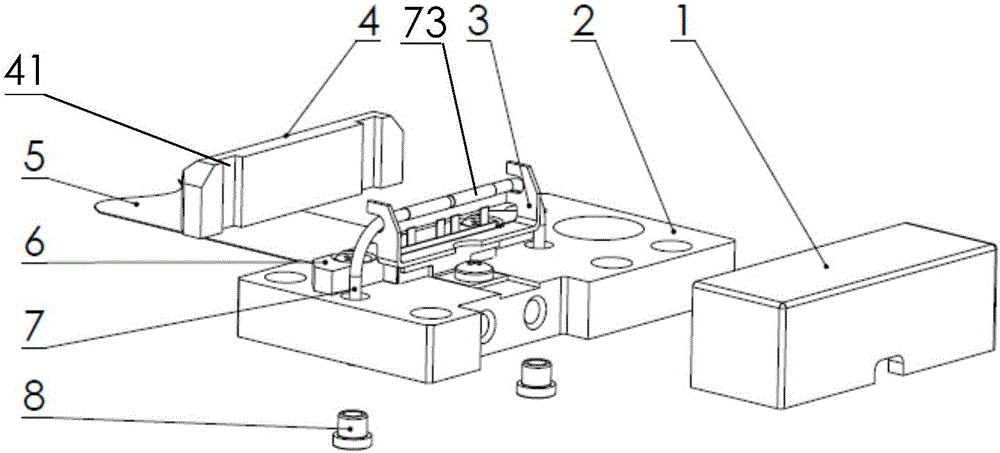
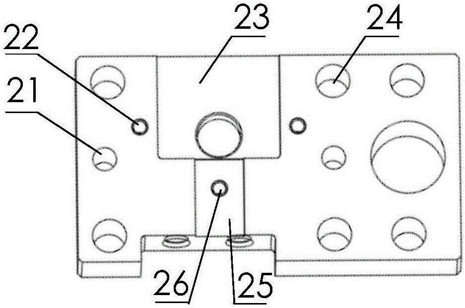
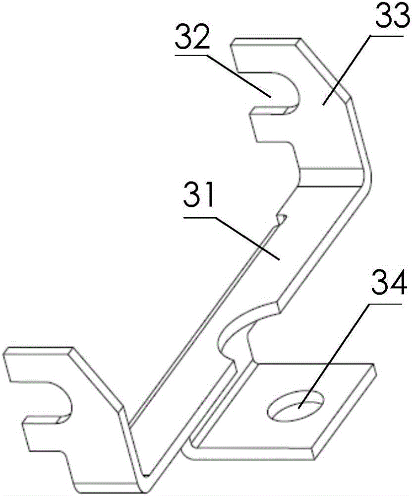
[0047] In the following specific embodiments of the present invention, please refer to figure 1 , figure 1 It is a schematic structural diagram of a disassembled state of a fluid delivery measuring device according to a preferred embodiment of the present invention; meanwhile, please refer to Figure 2-Figure 8 , Figure 2-Figure 8 yes figure 1 Sch...


PUM


Abstract

The invention discloses a fluid transportation measuring device, comprising a heat conducting frame, which is installed at the surface of the base, and provided with a pair of vertical brackets, wherein the brackets are provided with laterally opened buckle slots; a U-shaped sensing pipe, of which both ends in a horizontal middle part are respectively embedded in the buckle slots of two brackets and fixed to each other, wherein both ends of the bending part are respectively downwards crossed through the base in a sealing manner from the base surface, the horizontal middle part of the sensing oil is coiled with a sensing screw group; a pressing plate, which is installed at the base surface, and used or pressing the end part of a flat cable wire and fixing the end part on the base surface, wherein the flat cable wire is connected with a wiring head of the sensing screw group through a wiring terminal with an exposed end part; an outer cover, which is installed at the base surface, and used for covering the sensing pipe, the heat conducting frame and the pressing plate; the inner part of the outer cover is provided with a heat insulation type avoiding groove corresponding to appearances of the sensing pipe, the heat conducting frame, and the pressing plate. The fluid transportation measuring device can reduce the null shift, improve the anti-disturbing ability, reduce the sensitivity to the installing position, and realize the fluid transportation measurement with high precision and high response.

Description

technical field [0001] The present invention relates to the technical field of fluid measurement, and more particularly, to a fluid delivery measurement device. Background technique [0002] There are many types of measuring devices used to measure fluid flow, usually including volume flow and mass flow. Volume flow measurement is often affected by changes in working conditions such as temperature and pressure, and the measurement accuracy is affected. Therefore, in the occasions requiring precise metering, it is generally required to use a mass flow measurement device. In addition, according to the contact between the fluid and the device, it can be divided into two types: contact type and non-contact type. [0003] At present, the non-contact type is widely used in the industrial field because of its wide adaptability to the medium. Therefore, non-contact fluid mass flow measurement devices have important applications in scientific research and production in various fie...

Claims


Application Information

Patent Timeline
IPC IPC(8): G01F1/76G01F15/02G01F15/18
CPCG01F1/76G01F15/02G01F15/18
Inventor 苏乾益宋志辉杜井庆陈正堂
Owner BEIJING SEVENSTAR FLOW CO LTD
Why Eureka
Try Eureka