Method for realizing guided-mode resonance filtering through single gradient-material grating

A guided mode resonance filtering and guided mode resonance technology, applied in optics, optical filters, optical components, etc., can solve the problem of the deterioration of the scratch resistance and wear resistance of the film, weaken the mechanical and mechanical properties of the film, and the film layer. Adhesion is not very good and other problems, to achieve the effect of improving the anti-laser damage threshold, excellent anti-reflection characteristics, and eliminating restrictions

Active Publication Date: 2017-05-31
JIANGNAN UNIV
View PDF8 Cites 10 Cited by
  • Summary
  • Abstract
  • Description
  • Claims
  • Application Information

AI Technical Summary

Problems solved by technology

The traditional guided mode resonant grating is composed of multiple discrete film layers, and the refractive index between each film layer is abrupt, which brings many negative effects to the filter performance: (1) due to the mechanical properties of high and low refractive index materials The properties are different, such as the difference in thermal expansion coefficient, Young's modulus of elasticity, and Poisson's ratio. During the coating process, a large stress will be generated between the high and low refractive index film layers, and the adhesion between the film layers is not very good. This weakens the mechanical and mechanical properties of the entire film system, making the film's scratch resistance and abrasion resistance worse
(2) Due to the mismatch

Method used


Image

  • Method for realizing guided-mode resonance filtering through single gradient-material grating
  • Method for realizing guided-mode resonance filtering through single gradient-material grating
  • Method for realizing guided-mode resonance filtering through single gradient-material grating

Examples


Embodiment 1

[0019] Embodiment 1 Using a single graded material grating structure to design a guided mode resonant filter

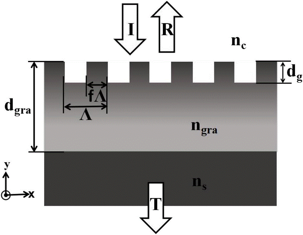
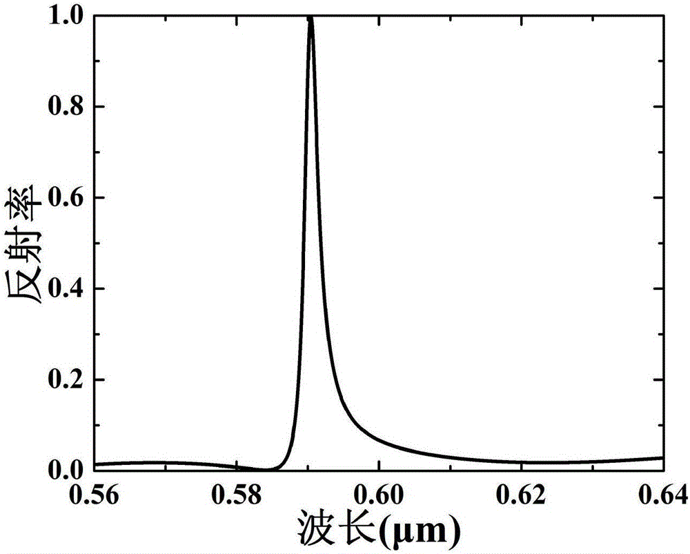
[0020] In this embodiment, we choose the normal incidence of TM polarized light, and the graded layer refractive index n gra ∈(1.5,2.1), which is n gra The size of the linear change in the range of 1.5-2.1, n 0 =1.5, the refractive index n of the substrate s = 2.1. When α=0.6, from formula (1), it can be known that the gradient layer thickness d gra = 1μm, select grating period Λ = 0.32μm, etching depth d g =0.1μm, grating duty cycle f=0.5, calculated by grating vector diffraction theory, guided mode resonance filtering can be realized at the channel position of 590.4nm, the peak wavelength reflectivity is 100%, and the spectral bandwidth is 2.4nm, next to the filter With a reflectivity lower than 3%, the filter has superior filtering performance, such as figure 2 shown.

[0021] In practical applications, the design wavelength and material of the filter can b...

Embodiment 2

[0022] Example 2 Changing the etching depth to select the channel position of a single graded material guided mode resonant filter

[0023] Based on the structural parameters of Example 1, under the condition of keeping other parameters constant, the channel position can be selected by selecting different etching depths.

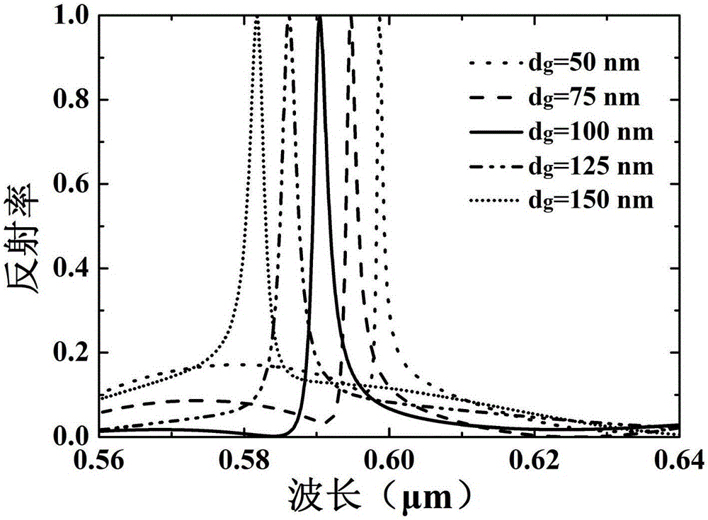
[0024] such as d g Take 50nm, 75nm, 100nm, 125nm, 150nm respectively, and use vector diffraction theory to calculate, get image 3 spectrum, it can be seen that when d g When increasing, the position of the filter channel moves to the short-wave direction, and the reflectivity at the peak wavelength reaches 100%. when d g When increasing from 50nm to 150nm, the position of the filter channel moves from 598.7nm to 581.8nm, and the reflection spectral bandwidth increases from 1.1nm to 2.8nm. Therefore, keeping other parameters constant, the channel position of the filter can be selected by selecting different etching depths.

Embodiment 3

[0025] Example 3 Adjusting the Gradient Coefficient α to Realize Guided Mode Resonance Multi-Channel Filtering

[0026]Under the parameters of Example 1, keep other parameters unchanged, and realize the control of the thickness of the gradient layer by adjusting the gradient coefficient α. When the thickness of the graded layer is larger, due to the multi-mode resonance effect of the guided mode resonance, the number of guided mode modes supported in the structure will be more, and the number of channels of the guided mode resonance filter will also be more. Therefore, by controlling the gradient coefficient α, the channel number of guided mode resonance can be controlled. That is, if the gradient coefficient α is reduced, the thickness of the graded-refractive index film layer increases, and the number of channels of the guided-mode resonant filter will increase.

[0027] In this example, we select three different parameters of α=0.75, α=0.5 and α=0.4 respectively, and use t...


PUM


Abstract

The invention discloses a method for realizing guided-mode resonance filtering through a single gradient-material grating structure, and belongs to the field of an optical communication and MOEM (micro optical electro mechanical) system. The method is characterized in that an optical thin film, the refractive index of which increases progressively with the thickness, is prepared on a substrate, and by etching the refractive-index-gradient thin film, a guided-mode resonant grating structure is obtained, and furthermore, guided-mode resonance filtering can be realized; on the basis of the above, by selecting different etching depths, channel position of a filter can be adjusted; and with the etching depth being kept unchanged, by reducing gradient coefficient, multichannel filtering can be realized. The filtering performance of the guided-mode resonant grating structure is highly insensitive to change of substrate refractive index, so that even if the substrate refractive index is higher than the maximum value of the refractive index of the gradient thin film, the guided-mode resonance filtering performance keeps excellent; and the method breaks away from the limit that refractive index of a waveguide layer in a conventional guided-mode resonance filter needs to be higher than the substrate refractive index, and is more advantageous in practical application.

Description

technical field [0001] The invention relates to a method for realizing guided-mode resonance filtering by using a single gradient material grating, in particular to a method for eliminating the restriction of the traditional guided-mode resonance filtering by the refractive index of the substrate, which belongs to the fields of optical communication and micro-opto-electromechanical. Background technique [0002] Guided mode resonant filter is an optical element that utilizes guided mode resonance effect to achieve resonance filtering. This type of filter requires less film layers and has superior filtering performance. It is used in laser high reflection systems, polarization systems, optical modulators and biological Sensing and other aspects have important application value. The traditional guided mode resonant grating is composed of multiple discrete film layers, and the refractive index between each film layer is abrupt, which brings many negative effects to the filter p...

Claims


Application Information

Patent Timeline
IPC IPC(8): G02B5/20
CPCG02B5/203
Inventor 桑田李俊浪王睿周健宇王跃科王继成王本新
Owner JIANGNAN UNIV
Why Eureka
Try Eureka