A Method of Using Single Graded Material Grating to Realize Guided Mode Resonant Filtering
A guided mode resonance filtering and guided mode resonance technology, applied in guided mode resonance filtering, to eliminate the traditional guided mode resonance filtering that is limited by the size of the substrate's refractive index, and can solve the problem of film scratch resistance and wear resistance. It is related to the problems of mechanical and mechanical properties, and the adhesion of the film layer is not very good, so as to achieve the effect of improving the anti-laser damage threshold, excellent anti-reflection characteristics, and eliminating limitations.
- Summary
- Abstract
- Description
- Claims
- Application Information
AI Technical Summary
Problems solved by technology
Method used
Image
Examples
Embodiment 1
[0019] Embodiment 1 Using a single graded material grating structure to design a guided mode resonant filter
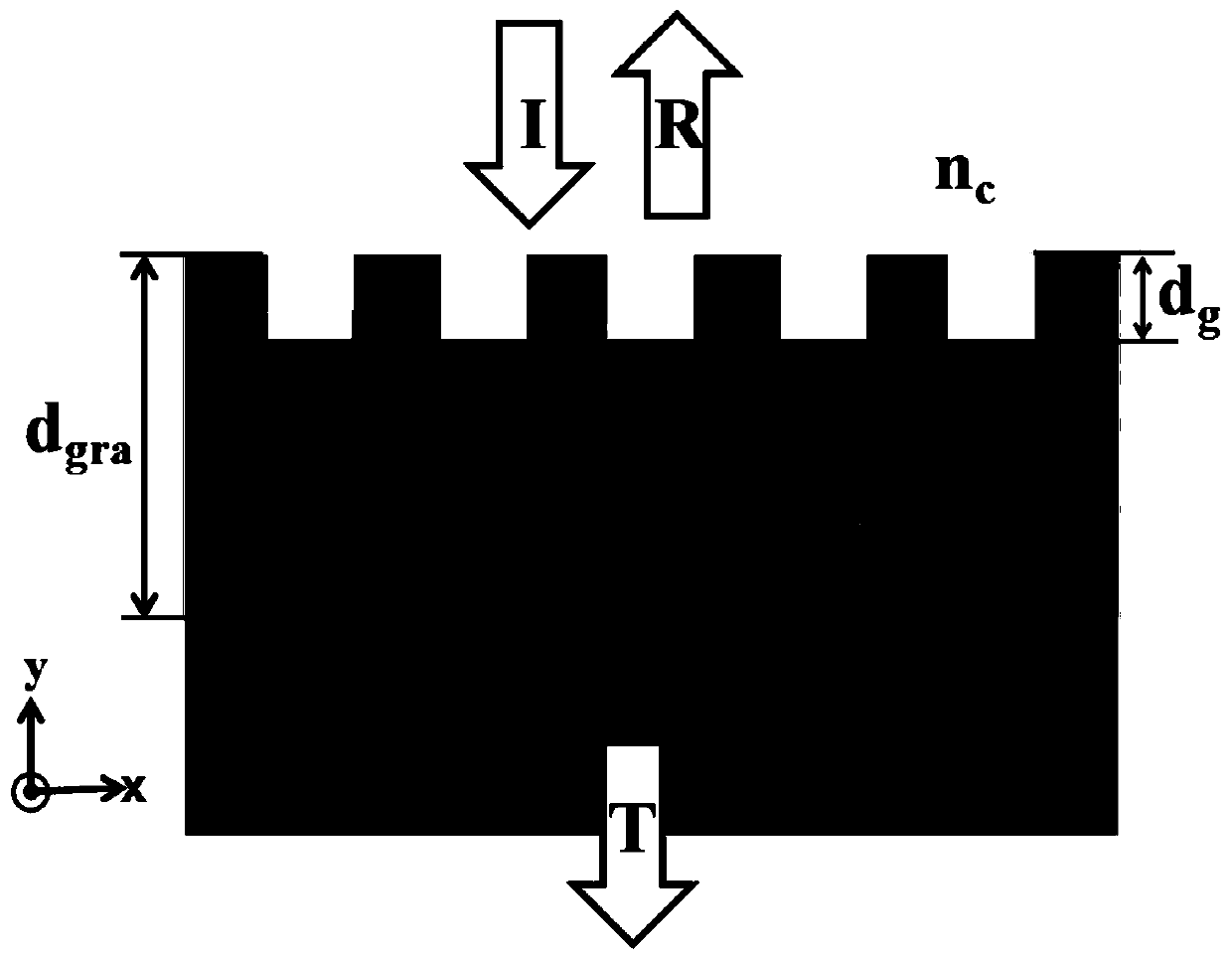
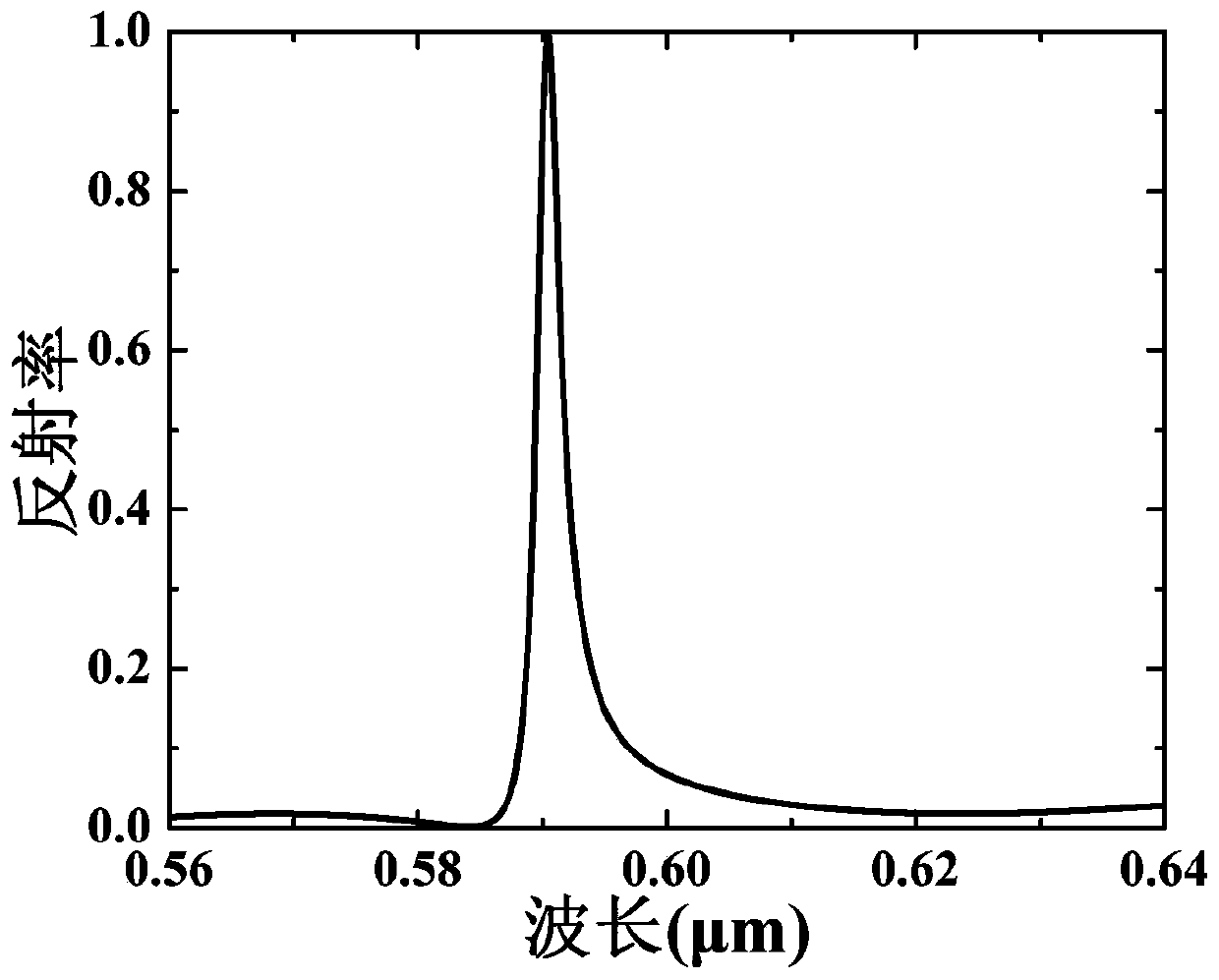
[0020] In this embodiment, we choose the normal incidence of TM polarized light, and the graded layer refractive index n gra ∈(1.5,2.1), which is n gra The size of the linear change in the range of 1.5-2.1, n 0 =1.5, the refractive index n of the substrate s = 2.1. When α=0.6, from formula (1), it can be known that the gradient layer thickness d gra = 1μm, select grating period Λ = 0.32μm, etching depth d g =0.1μm, grating duty cycle f=0.5, calculated by grating vector diffraction theory, guided mode resonance filtering can be realized at the channel position of 590.4nm, the peak wavelength reflectivity is 100%, and the spectral bandwidth is 2.4nm, next to the filter With a reflectivity lower than 3%, the filter has superior filtering performance, such as figure 2 shown.
[0021] In practical applications, the design wavelength and material of the filter can b...
Embodiment 2
[0022] Example 2 Changing the etching depth to select the channel position of a single graded material guided mode resonant filter
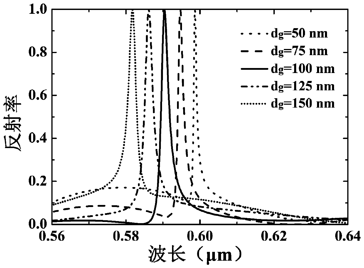
[0023] Based on the structural parameters of Example 1, under the condition of keeping other parameters constant, the channel position can be selected by selecting different etching depths.
[0024] such as d g Take 50nm, 75nm, 100nm, 125nm, 150nm respectively, and use vector diffraction theory to calculate, get image 3 spectrum, it can be seen that when d g When increasing, the position of the filter channel moves to the short-wave direction, and the reflectivity at the peak wavelength reaches 100%. when d g When increasing from 50nm to 150nm, the position of the filter channel moves from 598.7nm to 581.8nm, and the reflection spectral bandwidth increases from 1.1nm to 2.8nm. Therefore, keeping other parameters constant, the channel position of the filter can be selected by selecting different etching depths.
Embodiment 3
[0025] Example 3 Adjusting the Gradient Coefficient α to Realize Guided Mode Resonance Multi-Channel Filtering
[0026]Under the parameters of Example 1, keep other parameters unchanged, and realize the control of the thickness of the gradient layer by adjusting the gradient coefficient α. When the thickness of the graded layer is larger, due to the multi-mode resonance effect of the guided mode resonance, the number of guided mode modes supported in the structure will be more, and the number of channels of the guided mode resonance filter will also be more. Therefore, by controlling the gradient coefficient α, the channel number of guided mode resonance can be controlled. That is, if the gradient coefficient α is reduced, the thickness of the graded-refractive index film layer increases, and the number of channels of the guided-mode resonant filter will increase.
[0027] In this example, we select three different parameters of α=0.75, α=0.5 and α=0.4 respectively, and use t...
PUM
 Abstract
Description
Claims
Application Information
 - R&D
- Intellectual Property
- Life Sciences
- Materials
- Tech Scout
- Unparalleled Data Quality
- Higher Quality Content
- 60% Fewer Hallucinations
Browse by: Latest US Patents, China's latest patents, Technical Efficacy Thesaurus, Application Domain, Technology Topic, Popular Technical Reports.
© 2025 PatSnap. All rights reserved.Legal|Privacy policy|Modern Slavery Act Transparency Statement|Sitemap|About US| Contact US: help@patsnap.com


