Supercharge Your Innovation With Domain-Expert AI Agents!

Automatic verifying platform of programmable logic block based on System Verilog

An algorithm and platform technology, applied in the field of programmable logic algorithm block automatic verification platform, to avoid changes, improve verification efficiency, and ensure independence.

Inactive Publication Date: 2017-05-31
CHINA TECHENERGY +1
View PDF2 Cites 9 Cited by
  • Summary
  • Abstract
  • Description
  • Claims
  • Application Information

AI Technical Summary

Problems solved by technology

[0006] The purpose of the present invention is exactly at the situation of above-mentioned prior art, has proposed a kind of automatic verification platform of programmable logic algorithm block realized based on System Verilog, by using the mode of System Verilog virtual interface, realizes the reusability of platform, reduces due to test object The change of the platform is too large, which affects the efficiency of the test

Method used


Image

  • Automatic verifying platform of programmable logic block based on System Verilog
  • Automatic verifying platform of programmable logic block based on System Verilog
  • Automatic verifying platform of programmable logic block based on System Verilog

Examples


Embodiment 1

[0059] Embodiment 1: Verification of POW (power function) algorithm block

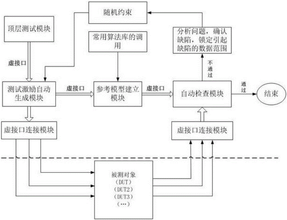
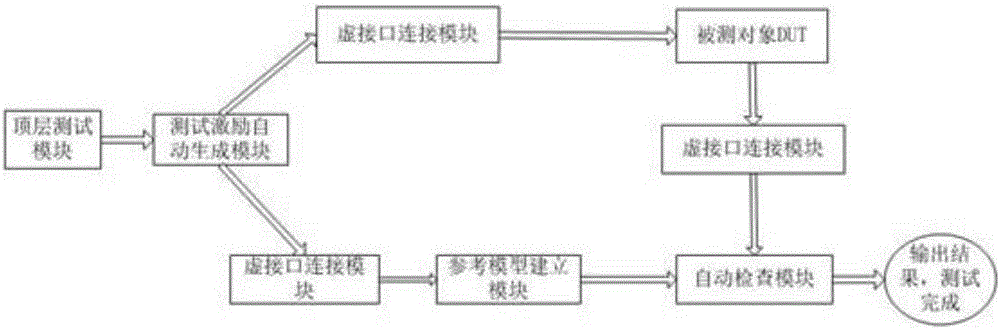
[0060] The POW algorithm block has two inputs, base and power, and one output. The three input types are in long real format. First, define the interface as real_sig_if. In the virtual interface connection module, declare the input, output, and input signals of the virtual interface type to be connected to the test stimulus automatic generation module and the automatic inspection module respectively. The output signal is connected to the automatic test stimulus module. The inspection modules are connected, and the top-level test module declares the input and output interface signals, which are respectively connected to the corresponding signals of the measured object and the virtual interface connection module. Call the test stimulus automatic generation module, which calls the random generation function randomize to generate the input data type that meets the requirements. In the reference model build...

Embodiment 2

[0061] Embodiment 2: verification of simulated manual algorithm block

[0062] The analog manual algorithm block includes 6 bool_signal type inputs, 10 real type parameter inputs and 5 bool_signal type outputs. The 6 input signals are controlled by the signal ena. When ena changes, the 6 input signals change together. According to this characteristic, create an interface declaration of bool_aman_if, including a bool type enable signal, and 6 input signals. The input signal of bool_aman_if, the actual parameter input of type real_sig_if, and the output signal of bool_sig_if are declared in the top-level test module. Call the virtual interface connection module in the top-level module to realize the connection between the interface of the object under test and the virtual interface connection module, call the test stimulus automatic generation module and the automatic inspection module, and connect the two modules through the virtual interface connection module. Call the random...


PUM


Abstract

The invention provides an automatic verifying platform of a programmable logic block based on System Verilog, comprising a top layer testing module, a testing excitation automatic generating module, a virtual interface connecting module, an algorithms library, a reference module establishing module and an automatic checking module. The top layer testing module starts a testing command, and data is generated by an automatic motivation generating module, and transmitted to a tested object and the reference model through the virtual interface connecting module; after receiving the data, the tested object treats the data as required; the reference model also treats the data; at last, the tested object and the reference model transmit the generated to the automatic checking module through the virtual interface connecting module so as to carry out the comparison treatment; the checking module outputs the comparison result. By applying the virtual interface method of System Verilog, the testing platform is separated from the tested object, thus the testing platform is not greatly changed along with the change of the testing object, and the reusing rate is high.

Description

technical field [0001] The invention relates to the field of FPGA simulation testing of nuclear power plants, in particular to an automatic verification platform for programmable logic algorithm blocks realized based on System Verilog. Background technique [0002] General nuclear power plant instrumentation and control equipment will involve the configuration of the algorithm block. In order to ensure the correctness of the algorithm block, it is necessary to carry out a detailed test of the algorithm block. There are many algorithm blocks involved in the configuration algorithm diagram, and as many examples as possible for each module are listed to ensure that the algorithm block can be used in a variety of case works correctly. If you use manual input to motivate, and then do the inspection method to do the test, it will lead to incomplete test case coverage, waste a lot of human resources and other problems. [0003] There are also automated tests for the test of the a...

Claims


Application Information

Patent Timeline
Patent Type & Authority Applications(China)
IPC IPC(8): G06F17/50
CPCG06F30/20G06F30/34
Inventor 董玲玲江国进白涛曹宗生周恩通吴飞宋立新冀建伟
Owner CHINA TECHENERGY
Features
  • R&D
  • Intellectual Property
  • Life Sciences
  • Materials
  • Tech Scout
  • Unparalleled Data Quality
  • Higher Quality Content
  • 60% Fewer Hallucinations
Learn More