Loaded angle radial logarithmic zigzag line micro-strip slow-wave structure based on photonic band gap structure

A slow-wave structure, photonic bandgap technology, which is applied to the circuit components of transit-time electron tubes and other directions, can solve the problems of increased process cost, reduced efficiency of traveling wave tube, and reduced performance and stability, and achieves increased process cost, The effect of increasing output power and reducing complexity

Active Publication Date: 2017-05-31
UNIV OF ELECTRONIC SCI & TECH OF CHINA
View PDF3 Cites 12 Cited by
  • Summary
  • Abstract
  • Description
  • Claims
  • Application Information

AI Technical Summary

Problems solved by technology

[0005] In view of the above-mentioned prior art, the purpose of the present invention is to provide an angular radial logarithmic meander microstrip slow-wave structure loaded based on a photonic bandgap structure, so as to solve the problem of electron injection deviating from the radial trajectory due to the electric field formed by charge accumulation on the dielectric substrate in the prior art , may cause damage to the microstrip slow-wave structur

Method used


Image

  • Loaded angle radial logarithmic zigzag line micro-strip slow-wave structure based on photonic band gap structure
  • Loaded angle radial logarithmic zigzag line micro-strip slow-wave structure based on photonic band gap structure
  • Loaded angle radial logarithmic zigzag line micro-strip slow-wave structure based on photonic band gap structure

Examples


Embodiment 1

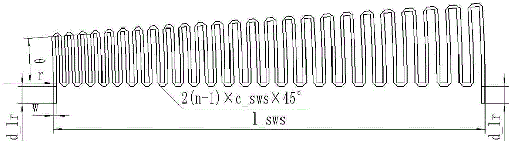
[0054]w is the width of the angle radial logarithmic microstrip meander, θ is the angular angle of the angle radial logarithmic microstrip meander, r is the initial radius of the logarithmic helix of the angle radial logarithmic microstrip meander, l_sws is the radial length of the angle radial logarithmic microstrip zigzag line, c_sws is the 45° chamfer length of the right angle bending of the angle radial logarithmic microstrip zigzag line, d_lr is the angle radial logarithmic microstrip zigzag line The length of the extended section at the input and output terminals, n is the number of cycles.

[0055] p is the width of the microstrip line constituting the photonic bandgap structure pattern, p1 is the side length of the square photonic bandgap structure, and p2 is the length of the local square pattern of the photonic bandgap structure.

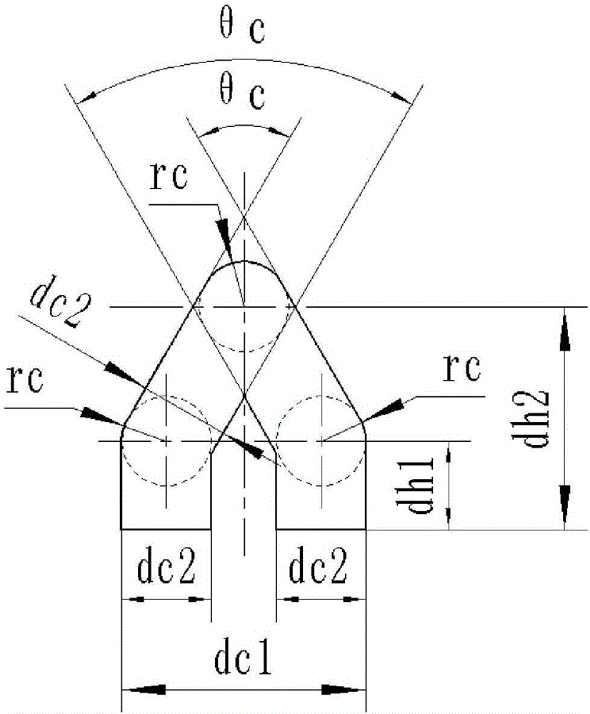
[0056] rc is the radius of the top of the side microstrip line and the arc at both ends, θc is the angle of the hypotenuse of the side mi...


PUM


Abstract

The invention discloses a loaded angle radial logarithmic zigzag line micro-strip slow-wave structure based on a photonic band gap structure, and belongs to the field of radial beam traveling wave tube slow-wave systems. The structure solves the technical problems that electron beams are deviated from radial tracks caused by an electric field formed by charge accumulation existing on a dielectric substrate, the damage of the micro-strip slow-wave structure and the deviation of the electron beams from effective interaction areas are possibly caused to cause the reduction of traveling wave tube efficiency, and the size of the traveling wave tube slow-wave system is decreased along with the increase of work efficiency and then the size of an electron beam passage is greatly reduced due to a size sharing effect so as to cause the increase of process cost and the reduction of performance and stability. The structure mainly comprises a dielectric substrate, angle radial logarithmic micro-strip zigzag lines, a photonic band gap structure and side micro-strip lines. The structure is used for a wave injection interaction system of radial beam traveling wave tubes.

Description

technical field [0001] The invention belongs to the field of radial-beam traveling-wave tube slow-wave systems, and in particular relates to an angular radial logarithmic zigzag line microstrip slow-wave structure loaded based on a photonic bandgap structure. Background technique [0002] As a microwave power device, traveling wave tubes have the characteristics of wide frequency band, high power, high efficiency, large gain and long life. They are widely used in electronic countermeasures and military-civilian communications. Their performance determines the overall level of the equipment. [0003] Currently commonly used helical traveling wave tubes, coupled cavity traveling wave tubes, folded waveguide traveling wave tubes, etc., due to the size co-existence effect, the size of the slow wave structure will decrease with the increase of the operating frequency, resulting in high frequency operation, The size of the electronic injector channel is greatly compressed, requiri...

Claims


Application Information

Patent Timeline
IPC IPC(8): H01J23/24
CPCH01J23/24
Inventor 李新义宫玉彬王战亮魏彦玉段兆云巩华荣
Owner UNIV OF ELECTRONIC SCI & TECH OF CHINA
Why Eureka
Try Eureka