Dual-motor cooperative control system and method

A collaborative control, dual-motor technology, applied in the direction of speed regulation of multiple motors, can solve the problems of error control accuracy, high system cost, complex collaborative control instructions, etc., to eliminate differences, simple system structure, and improve collaborative control performance. Effect

Pending Publication Date: 2017-05-31
常州寻心电子科技有限公司
View PDF5 Cites 19 Cited by
  • Summary
  • Abstract
  • Description
  • Claims
  • Application Information

AI Technical Summary

Problems solved by technology

[0009] The purpose of the present invention is to overcome the defects of complex cooperative control instructions, high system cost, easy to generate errors and low control precision in the prior art, and provide a dual-motor cooperative control system with high cost performance, simple system structure and high control precision. method

Method used


Image

  • Dual-motor cooperative control system and method
  • Dual-motor cooperative control system and method
  • Dual-motor cooperative control system and method

Examples


Embodiment 1

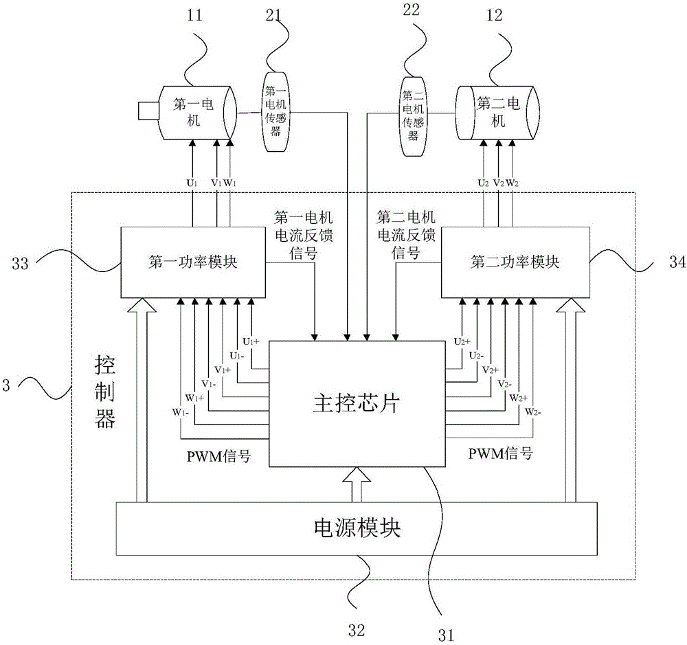
[0044] In this embodiment, the first motor sensor 21 and the second motor sensor 22 are position sensors, which respectively perform coordinated control on the position / displacement, speed and torque of the two motors.

[0045] In this embodiment, the currents of the first motor 11 and the second motor 12 are respectively closed-loop controlled, and the respective positions and speeds of the first motor 11 and the second motor 12 are no longer respectively closed-loop controlled, but the first motor The position difference and speed difference between 11 and the second motor 12 are closed-loop controlled.

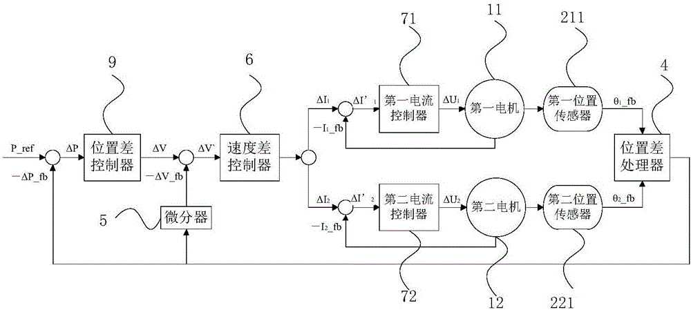
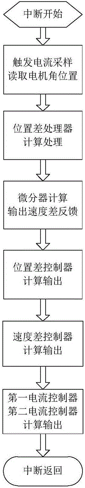
[0046] Such as figure 2 with image 3 As shown, the position cooperative control method for dual motors is as follows: after the position control interruption starts, trigger current sampling to obtain the feedback current I1_fb of the first motor 11 and the feedback current I2_fb of the second motor 12, and simultaneously read the first position sensor 211 to detect The...

Embodiment 2

[0050] In this embodiment, the first motor sensor 21 and the second motor sensor 22 are speed sensors, such as Figure 8 with Figure 9 As shown, the dual-motor speed cooperative control method is as follows: after the speed control interruption starts, trigger current sampling to obtain the feedback current I1_fb of the first motor 11 and the feedback current I2_fb of the second motor 12, and simultaneously read the detected output of the first speed sensor 212 The feedback speed V1_fb and the second speed sensor 222 detect the output feedback speed V2_fb; the speed difference processor 10 outputs the feedback speed difference ΔV_fb through calculation and processing according to the feedback speed V1_fb and the feedback speed V2_fb; the speed difference controller 6 according to the speed command V_ref and the feedback speed The difference ΔV of the difference ΔV_fb is calculated by calculating the output current difference target values ​​ΔI1 and ΔI2; the first current cont...


PUM


Abstract

The invention belongs to the technical field of motor drive control, and specifically relates to a dual-motor cooperative control system and method. The system comprises a first motor, a first motor sensor, a second motor, a second motor sensor and a controller, wherein the controller comprises a main control chip, a power supply module, a first power module and a second power module; and the main control chip receives signals of the first motor sensor and the second motor sensor and current feedback signals of the first motor and the second motor, and respectively obtains multi-phase PWM signals for driving the first motor and the second motor through a control algorithm, and the first power module and the second power module generate corresponding multi-phase voltage signals to respectively drive the first motor and the second motor after receiving the multi-phase PWM signals. The control method comprises the following steps: respectively performing closed-loop control on the current of the two motors, and performing closed-loop control on the position difference and/or displacement difference and/or speed difference between the two motors. The dual-motor cooperative control system and method disclosed by the invention have the advantages of high cost performance, simple system structure and high control precision.

Description

technical field [0001] The invention belongs to the technical field of motor drive control, and in particular relates to a dual-motor cooperative control system and method. Background technique [0002] In modern mechanical devices, cooperative control of multiple motors is often required, the most common of which is dual-motor cooperative control. For example: a trolley equipped with two independent power wheels and no differential, relies on the synchronous rotation of the two wheels to achieve straight walking, and relies on the differential motion of the two wheels to achieve turning. Another example is the dual-motor coaxial control used when driving a long shaft or a flexible shaft, which requires the two motors to operate highly synchronously. [0003] The existing dual-motor cooperative control system adopts a system structure in which one command unit controls two motor drive units, and controls the two motors by relying on the difference or synchronization of the ...

Claims


Application Information

Patent Timeline
Patent Type & Authority Applications(China)
IPC IPC(8): H02P5/48
Inventor 刘杰蔡一石晶合
Owner 常州寻心电子科技有限公司
Why Eureka
Try Eureka