Drive circuit

A technology for driving circuits and circuit output, applied in circuits, electrical components, electronic switches, etc., can solve problems such as large EMI noise, and achieve the effects of eliminating overshoot and oscillation, high efficiency, and speeding up the flipping speed.

Active Publication Date: 2017-05-31
SHANGHAI BEILING
View PDF4 Cites 10 Cited by
  • Summary
  • Abstract
  • Description
  • Claims
  • Application Information

AI Technical Summary

Problems solved by technology

[0005] The technical problem to be solved by the present invention is to overcome the defect of large EMI noise in the drive circuit of th...

Method used


Image

  • Drive circuit
  • Drive circuit
  • Drive circuit

Examples


Embodiment Construction

[0027] The present invention is further illustrated below by means of examples, but the present invention is not limited to the scope of the examples.

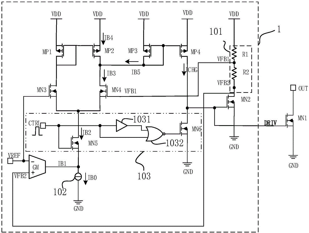
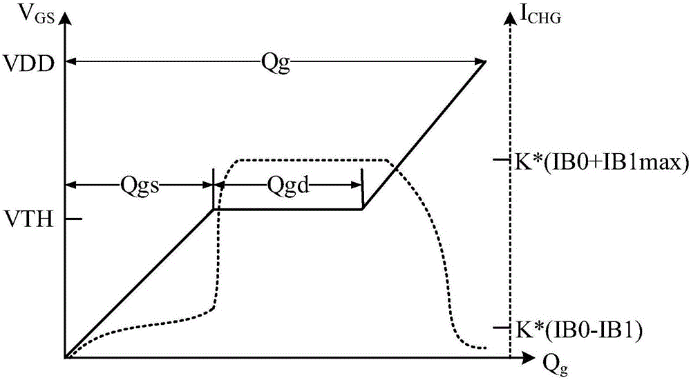
[0028] Such as figure 2 and image 3 As shown, a driving circuit 1 is used to drive an N-type power switch tube MN1. The driving circuit 1 includes a circuit output terminal DRIV, a transconductance amplifier GM, a constant current source 102, a first PMOS transistor MP1, a second PMOS transistor MP2, a third PMOS transistor MP3, a fourth PMOS transistor MP4, a second NMOS transistor MN2, and a second PMOS transistor MP4. Three NMOS transistors MN3, a fourth NMOS transistor MN4, a voltage divider circuit 101 and a power transistor shutdown circuit 103; the voltage divider circuit 101 includes a first resistor R1 and a second resistor R2. The power transistor shutdown circuit 103 includes a fifth NMOS transistor MN5 , a sixth NMOS transistor MN6 , a delay circuit 1031 and a NOR gate 1032 . Wherein, the second NMOS transisto...


PUM


Abstract

The invention discloses a drive circuit. The drive circuit comprises a circuit output end, a transconductance amplifier, a constant-current source, a first PMOS (p-channel metal oxide semiconductor) tube, a second PMOS tube, a third PMOS tube, a fourth PMOS tube, a second NMOS (n-channel metal oxide semiconductor) tube, a third NMOS tube, a fourth NMOS tube and a bleeder circuit. The bleeder circuit is serially connected between a drain electrode of the second NMOS tube and supply voltage, the bleeder circuit is used for outputting a first feedback voltage and a second feedback voltage, the first feedback voltage is larger than the second feedback voltage, and the circuit output end is used for driving a grid electrode of an N-type power switch tube. By reasonable control of charging and discharging current of the grid electrode of the to-be-driven N-type power switch tube, a voltage change rate of the grid electrode of the to-be-driven N-type power switch tube is controlled, an overturning process including slow overturning, quick overturning and slow overturning in sequence at different overturning stages of the N-type power switch tube is realized, and accordingly electromagnetic interference noises can be reduced while high efficiency in power output can be guaranteed.

Description

technical field [0001] The invention belongs to the technical field of power switch chips, and in particular relates to a driving circuit. Background technique [0002] In the application fields of power switch tubes, including Class D audio power amplifiers, switching power supplies, and LED (light-emitting diode) drivers, small and medium power applications basically use integrated power switch tubes, and integrated power switch tubes generally require gate drive. The signal has a larger charge and discharge current in order to make the switch steeper to improve efficiency. [0003] A classic drive circuit is usually composed of a chain of tapered inverters. Such as figure 1 As shown, among them, the driving capability of the inverter chain increases step by step, and finally gives the gate capacitance C of the power tube G Fast charge and discharge. When the power switch tube is turned over, the rapid change of the gate voltage and current causes the power switch tube...

Claims


Application Information

Patent Timeline
IPC IPC(8): H03K17/042H03K17/16
CPCH03K17/04213H03K17/168
Inventor 刘燕涛刘伦
Owner SHANGHAI BEILING
Why Eureka
Try Eureka