Gas turbine, combined cycle plant, and method of starting a gas turbine

A technology for gas turbines and turbines, which is applied in the direction of gas turbine devices, combined combustion mitigation, and engine start-up, which can solve the problems of reduced driving force recovery efficiency and reduced performance of gas turbines, and achieve a small degree of reduction and the effect of suppressing thermal expansion

Active Publication Date: 2018-04-27
MITSUBISHI POWER LTD
View PDF4 Cites 0 Cited by
  • Summary
  • Abstract
  • Description
  • Claims
  • Application Information

AI Technical Summary

Problems solved by technology

In this case, there is a problem that when the distance between the tip of the turbine blade and the inner peripheral surface of the turbine block is set according to the distance when the gas turbine is started, the distance is enlarged when the gas turbine is operated in a steady state. to more than demanded and leads to a reduction in the recovery efficiency of the driving force generated by the turbine and a reduction in the performance of the gas turbine itself

Method used


Image

  • Gas turbine, combined cycle plant, and method of starting a gas turbine
  • Gas turbine, combined cycle plant, and method of starting a gas turbine
  • Gas turbine, combined cycle plant, and method of starting a gas turbine

Examples


Embodiment Construction

[0037] Preferred embodiments of the gas turbine, the combined cycle unit, and the start-up method of the gas turbine according to the present invention will be described in detail below with reference to the accompanying drawings. In addition, this invention is not limited to this embodiment, Moreover, when it has several embodiment, the aspect which combined each embodiment is also included.

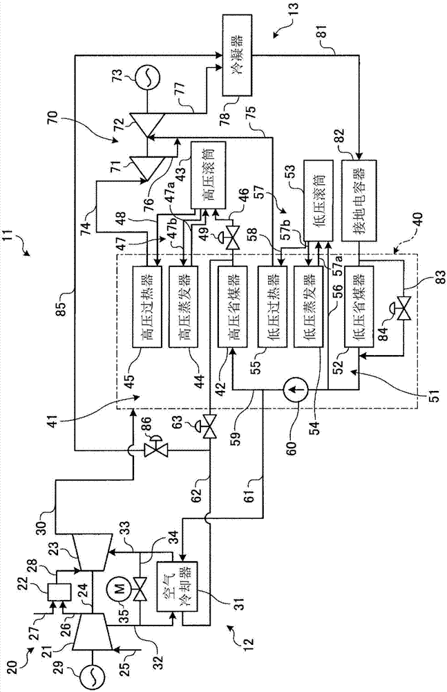
[0038] figure 1 is a schematic configuration diagram showing a gas turbine combined cycle plant according to the present embodiment.

[0039] In this example, if figure 1 As shown, the gas turbine combined cycle unit 11 is composed of a gas turbine section 12 and a steam turbine section 13 . The gas turbine section 12 has a gas turbine 20 . This gas turbine 20 has a compressor 21 , a combustor 22 , and a turbine 23 , and the compressor 21 and the turbine 23 are integrally and rotatably connected via a rotating shaft (rotor) 24 . The compressor 21 compresses the air sucked in from th...


PUM


Abstract

According to the start-up method of the gas turbine, the combined cycle unit and the gas turbine of the present invention, by setting: an air cooler (31), which performs heat exchange with the compressed air extracted from the compressor (21) and supplies the cooled compressed air To the cooling system of the rotor system of the turbine (23); the air cooler bypass line (34), which bypasses the compressed air introduced into the air cooler (31); the electric valve (35), which is arranged at the air cooler On the bypass pipeline (34); and the control part (101), which controls the opening and closing of the electric valve (35), so that the valve opening of the electric valve (35) is a low level opening during the start-up process of the gas turbine (20). When the load of the gas turbine (20) rises, the valve opening of the electric valve (35) is larger than the low level opening, so that the distance between the turbine cylinder side and the rotor blade is set to an appropriate amount, and the safety can be realized. Ensuring and performance improvements.

Description

technical field [0001] For example, the present invention relates to a gas turbine that supplies fuel to compressed high-temperature, high-pressure air and burns it, and supplies the generated combustion gas to a turbine to obtain rotational power, a combined cycle unit to which the gas turbine is applied, and the gas turbine start method. Background technique [0002] A typical gas turbine consists of a compressor, a combustor and a turbine. The compressor generates high-temperature, high-pressure compressed air by compressing the air sucked in from the intake port. The combustor supplies fuel to the compressed air and burns it to obtain high-temperature, high-pressure combustion gas. The turbine is driven by the combustion gas, and drives a coaxially connected generator. [0003] The turbine mechanism of this gas turbine is such that a plurality of stationary vanes and moving vanes are alternately arranged in the cylinder along the flow direction of the combustion gas, ...

Claims


Application Information

Patent Timeline
Patent Type & Authority Patents(China)
IPC IPC(8): F01D25/12F01D11/24F01D25/00F01K23/10F02C7/18F02C7/28
CPCF01D11/24F01D25/12F01K23/10F02C7/18F02C7/28Y02E20/16F01D19/00F05D2260/213F05D2220/72F01K23/08F02C7/185Y02T50/60F02C3/04F02C6/18F02C9/18
Inventor 井上昌和村上雅幸
Owner MITSUBISHI POWER LTD
Why Eureka
Try Eureka