
Steel shot production line

A production line and steel shot technology, applied in the field of steel shot production, can solve the problems of low production efficiency, achieve the effect of improving efficiency and avoiding irregular expansion

Active Publication Date: 2017-06-13
南通壹选智能科技有限公司
View PDF7 Cites 4 Cited by
  • Summary
  • Abstract
  • Description
  • Claims
  • Application Information

AI Technical Summary

Problems solved by technology

In the actual production process, each process of steel shot processing is set up separately, and the steel shot needs to be transported separately during the processing of each process, which makes the production efficiency low

Method used


Image

  • Steel shot production line
  • Steel shot production line
  • Steel shot production line

Examples


Embodiment Construction

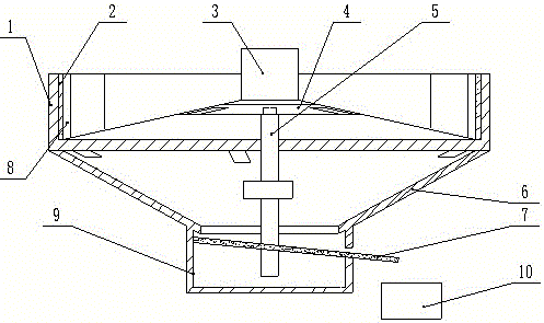
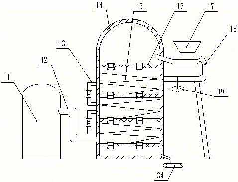
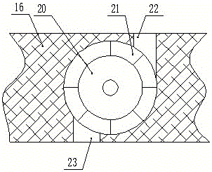
[0016] Explanation of reference numerals: quenching pool 1, magnet 2, centrifuge 3, cone 4, return pipe 5, funnel chamber 6, screen plate 7, drain pipe 8, water tank 9, feeding cart 10, hot blast stove 11, hot air pipe 12. Pressure relief pipe 13, furnace body 14, slide rail 15, partition 16, first feeding hopper 17, release pipe 18, release valve 19, transfer roller 20, steel shot groove 21, feed channel 22, outlet Material channel 23, screening box 24, motor 25, screening channel 26, collection box 27, second feeding hopper 28, feeding pipe 29, mesh screen 30, air duct 31, fan 32, connecting column 33, conveyor belt 34.

[0017] Such as figure 1 As shown, the steel shot collection device of the steel shot production line includes a quenching pool 1, a centrifuge 3 is located in the middle of the quenching pool 1, a layer of magnets 2 is arranged on the inner wall of the quenching pool 1, and a funnel cavity 6 is connected to the bottom of the quenching pool 1. The bottom of...


PUM


Abstract

The invention relates to the technical field of steel shot production, in particular to a steel shot production line. The steel shot production line comprises a centrifugal machine, a steel shot collecting device, a tempering furnace and a screening device, wherein the steel shot collecting device comprises a quenching bath; a frustum protruding upwards is arranged in the middle of the quenching bath; the centrifugal machine is mounted at the top of the frustum; steel shots thrown out by the centrifugal machine enter the quenching bath and are collected and then poured into a feed hopper of the tempering furnace through a skip, so that tempering treatment of the steel shots is started; and after finish of tempering, the steel shots are fed into a second feed hopper through a conveyor belt to be screened, so that the finally obtained steel shots are all screened, and accordingly, the steel shot production efficiency is improved.

Description

technical field [0001] The invention relates to the technical field of steel shot production, in particular to a steel shot production line. Background technique [0002] Steel shot is a kind of spherical particle made of special material through special heat treatment. In the preparation process of steel shot, the equipment generally used is a centrifuge, which melts the high-carbon steel and pours it into the rotating centrifugal brick, and then relies on the centrifugal force of the centrifuge to throw out steel shots of various sizes. The discharged steel shot will fall into the quenching pool for rapid cooling to form a shot body, and finally the formed shot body will be collected for reheating and tempering, so that the shot body can reach the required hardness. In the actual production process, each process of steel shot processing is set up separately, and the steel shot needs to be transported separately during the processing of each process, so that the production...

Claims


Application Information

Patent Timeline
Patent Type & Authority Applications(China)
IPC IPC(8): B22F9/10B22D13/00
CPCB22D13/00B22F9/10
Inventor 苏祖弟
Owner 南通壹选智能科技有限公司
Learn More