Electric spark liquid atomization nozzle

A technology for atomizing nozzles and EDM fluids, applied in the field of EDM, can solve the problems of unstable machining, low machining efficiency, increased probability of abnormal discharge, etc., so as to change the discharge gap and discharge channel configuration, improve the workpiece Surface quality, the effect of improving the atomization state

Active Publication Date: 2017-06-13
江苏天凤源食品有限公司
View PDF6 Cites 7 Cited by
  • Summary
  • Abstract
  • Description
  • Claims
  • Application Information

AI Technical Summary

Problems solved by technology

[0002] Traditional EDM uses oil as the discharge medium, which has stable processing and high efficiency, but there are also some disadvantages: the gas decomposed by pyrolysis is harmful to the human body and the environment; there is a fire hazard; the waste after use is harmful to the environment; and the use cost is high ; There are heat-affected layers such as white layer on the processed surface
Oil-based working fluid is used in EDM, but there are some problems, such as large heat loss, poor chip removal effect, easy to form white layer due to rapid cooling, and easy to rust the machine tool
In the 1990s, the Kunieda Masonic scholar of Tokyo University of Agriculture and Technology proposed and realized the gas dielectric EDM, which effectively solved the above-mentioned shortcomings of the oil-based working fluid, but the gas dielectric discharge gap is very small, and the requirements for the machine tool servo system are high. The processing is unstable when using ordinary EDM machine tools, which increases the probability of abnormal discharge and reduces the effective pulse utilization rate, so the processing efficiency is low

Method used


Image

  • Electric spark liquid atomization nozzle
  • Electric spark liquid atomization nozzle
  • Electric spark liquid atomization nozzle

Examples


Embodiment 1

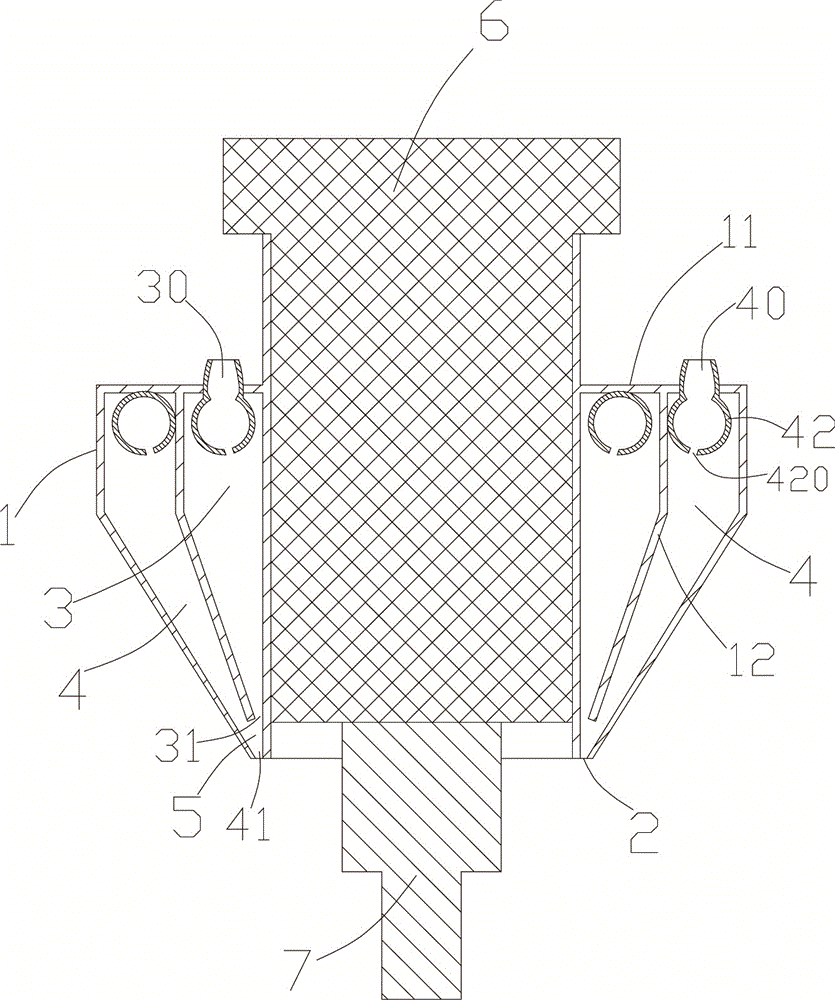
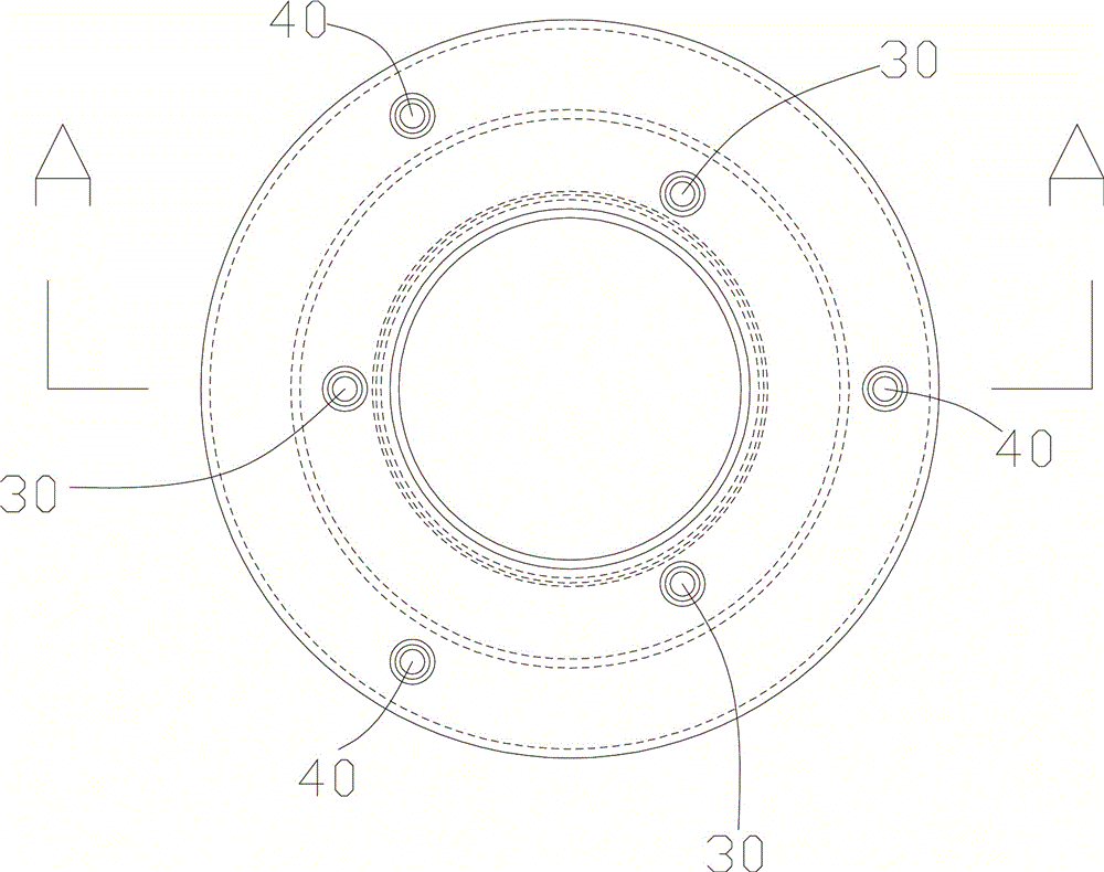
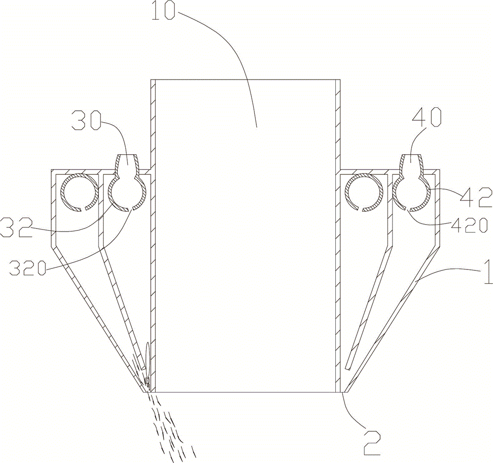
[0015] Embodiment 1: see Figure 1 to Figure 3 Shown is a specific embodiment of an EDM fluid atomizing nozzle of the present invention. The EDM liquid atomizing nozzle includes a nozzle main body 1, the nozzle main body 1 includes a hollow tube 10 for installing the electrode 7, the upper end of the hollow tube 10 exceeds the nozzle main body 1, and the distance between the EDM machine fixture 6 and the nozzle main body 1 The inner surface of the hollow tube 10 and the outer surface of the EDM fixture 6 are a transition fit, and the electrode 7 is fixed on the front end of the EDM fixture 6. The nozzle body 10 has a sealed upper end cover 11 and an opening The lower end of the nozzle, the hollow tube 10 runs through the nozzle body 1 and extends to the opening 2 provided at the lower end, an annular partition 12 is arranged in the nozzle body 1, and the nozzle body 1 is divided into a liquid chamber 3 and the gas chamber 4, the upper end cover 11 is respectively provided wit...

Embodiment 2

[0021] Embodiment 2: The gaps between the first annular seam and the second annular seam are both 2 mm, and other technical solutions are the same as in Embodiment 1.


PUM


Abstract

The invention discloses an electric spark liquid atomization nozzle and belongs to the technical field of electric spark machining. The electric spark liquid atomization nozzle comprises a nozzle main body. The nozzle main body comprises a hollow tube used for installing an electrode and is provided with a sealed upper end cover and an open lower end. The hollow tube penetrates through the nozzle main body and extends to an opening formed in the lower end. The nozzle main body is internally provided with an annular partition plate which divides the nozzle main body into a liquid chamber and a gas chamber. The lower end of each liquid inlet is provided with a first annular groove. The lower end of each gas inlet is provided with a second annular groove. A mixing chamber is arranged at an opening in the lower end of the liquid chamber and an opening in the lower end of the gas chamber. Compared with the prior art, the electric spark liquid atomization nozzle can improve the atomization state and then change the discharge gap and the discharge channel configuration, so that the workpiece surface quality is improved, the clearance rate of electric corrosion products is accelerated, the machining capacity of existing electric spark machine tools is further excavated, and the electric spark machining technology is efficient.

Description

technical field [0001] The invention belongs to the technical field of electric discharge machining, and in particular relates to an electric discharge fluid atomizing nozzle. Background technique [0002] Traditional EDM uses oil as the discharge medium, which has stable processing and high efficiency, but there are also some disadvantages: the gas decomposed by pyrolysis is harmful to the human body and the environment; there is a fire hazard; the waste after use is harmful to the environment; and the use cost is high ; There are heat-affected layers such as white layer on the processed surface. Oil-based working fluid is used in EDM, but there are some problems, such as large heat loss, poor chip removal effect, easy to form white layer due to rapid cooling, and easy to rust the machine tool. In the 1990s, the Kunieda Masonic scholar of Tokyo University of Agriculture and Technology proposed and realized the gas dielectric EDM, which effectively solved the above-mentione...

Claims


Application Information

Patent Timeline
Patent Type & Authority Applications(China)
IPC IPC(8): B23H1/10
CPCB23H1/10
Inventor 戴睿赵康东梁荣徐赞周秋鸿
Owner 江苏天凤源食品有限公司
Why Eureka
Try Eureka