Device and method for compositely machining curved hole through magnetic field guide and electrolysis electric sparks

A composite machining, magnetic field guided technology, applied in electric machining equipment, metal machining equipment, circuits, etc., can solve the problems of affecting the roughness and accuracy of machining holes, irregular vibration of springs, and difficult to control machining gaps, and improve machining stability. performance, avoid short-circuit phenomenon, and ensure the effect of machining accuracy

Inactive Publication Date: 2017-06-13
JIANGSU UNIV
View PDF8 Cites 7 Cited by
  • Summary
  • Abstract
  • Description
  • Claims
  • Application Information

AI Technical Summary

Problems solved by technology

Using the spring in a compressed state to bend and elongate with different curvatures to drive the electrode processing method can process a curved hole in a predetermined direction, but there are problems of low processing efficiency and irregular vibration of the spring, which affects the roughness and accuracy of the processed hole.
The method of using shape memory alloys as bending guides can also process curved holes based on the principle of heat deformation of memory alloys, but the electrode head is easily unstable during processing, and the shape,

Method used


Image

  • Device and method for compositely machining curved hole through magnetic field guide and electrolysis electric sparks
  • Device and method for compositely machining curved hole through magnetic field guide and electrolysis electric sparks

Examples


Embodiment

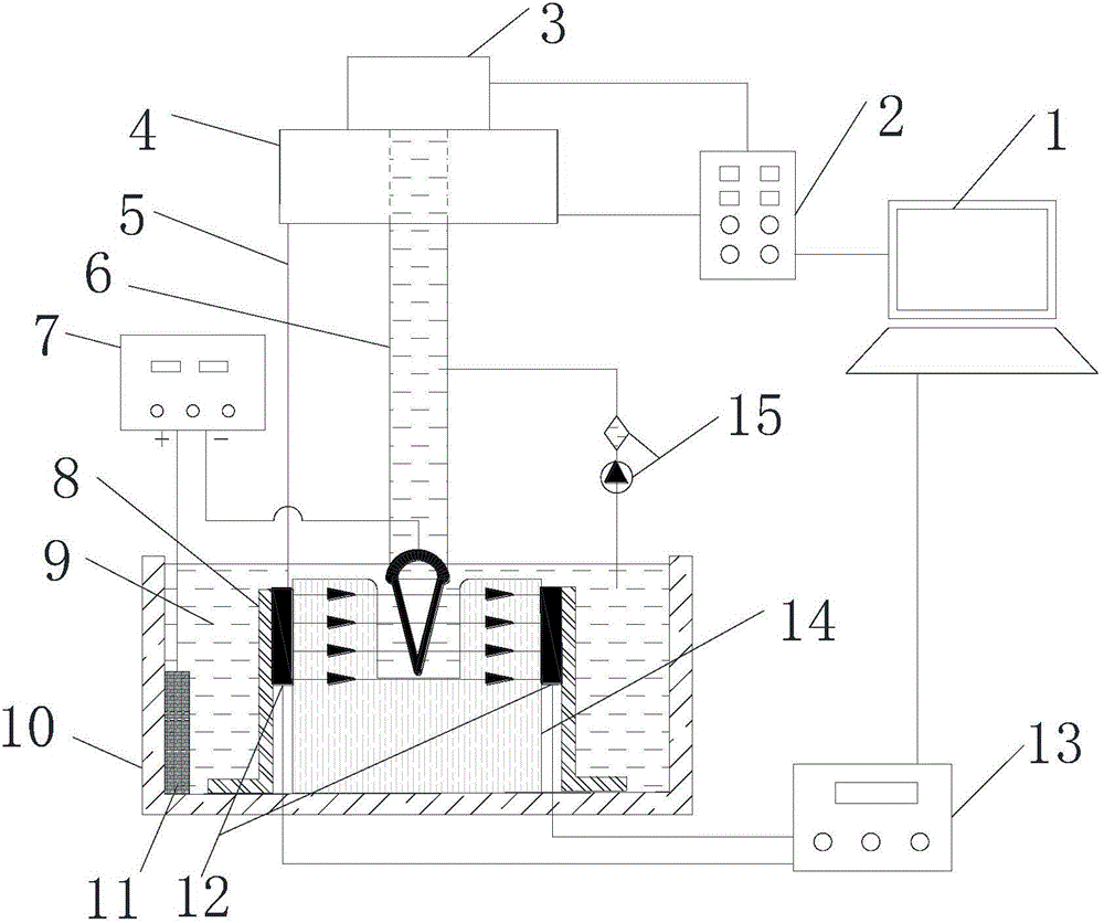
[0035] Embodiment: combine below figure 1 with figure 2 Describe in detail the use details and working conditions of the method and device of the present invention.

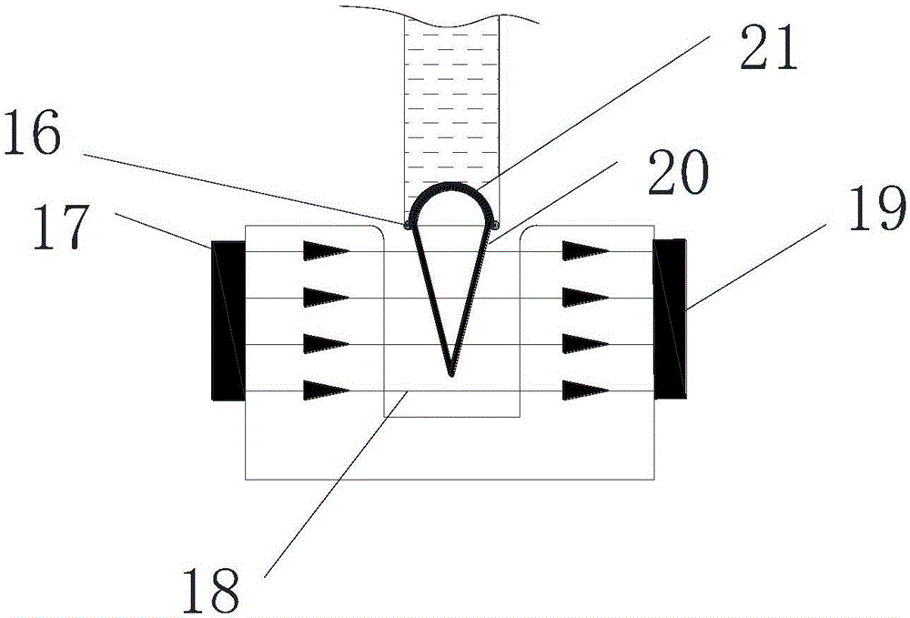
[0036]Wherein the electrolyte 9 is an alkaline solution, the tool electrode 20 adopts a steel conical electrode, the workpiece 14 is a non-magnetic material, and the auxiliary electrode 11 adopts a graphite electrode; the conical top of the tool electrode 20 needs to be immersed in the electrolyte 9, and the conical bottom can be Rotating freely in the universal joint 21, the voltage of the adjustable pulse power supply 7 is 0-60V, the frequency is 1-5000Hz, and the duty cycle is 0-100%.

[0037] The present invention uses method as follows:

[0038] Install the slide rail 8 on the water tank 10, install the guide ring 12 composed of the left electromagnetic device 17 and the right electromagnetic device 19 on the slide rail 8 and connect it with the corner stepping motor 4 through the connecting rod 5; adjust...


PUM

PropertyMeasurementUnit
Diameteraaaaaaaaaa

Abstract

The invention discloses a device and method for compositely machining a curved hole through magnetic field guide and electrolysis electric sparks. The method and the device are suitable for micro machining of non-magnetic materials and belong to the field of non-traditional machining in a manufacturing technology. According to the device and the method, a guide ring comprises a left electromagnetic device and a right electromagnetic device, wherein the left electromagnetic device and the right electromagnetic device load voltage to generate different magnetic fields through a digitally controlled stabilized voltage supply; the guide ring is arranged in a sliding rail to continuously output magnetic field force to an electrode; a tool electrode generates a tilt angle in a universal joint due to the magnetic field force; a flexible hose is fed along the swing direction of the tool electrode under the drive of a vertical feed motor; the tool electrode is electrochemically discharged in the direction to etch off a workpiece material; a circulating pump in the device conveys an electrolyte to the flexible hose, and the electrolyte flows to the electrode through a reserved micro-pore in the universal joint, thereby achieving the effects of discharging scraps and supplementing the electrolyte; and a computer in the device controls the magnetic field intensity through regulating output voltage of the digitally controlled stabilized voltage supply, and the rotating speed and the corner of a corner stepper motor and the feed velocity of a vertical feed motor are controlled through a control card.

Description

technical field [0001] The invention relates to the field of special processing in manufacturing technology, in particular to a device and method for combined processing of curved holes by electrolysis and electric spark guided by a magnetic field. Background technique [0002] With the development of industry and the improvement of living standards, people's demand for high-precision injection molded parts continues to increase, which has higher requirements for mold precision in the injection mold industry. However, accurate temperature control during the cooling process has become an obstacle to the continuous improvement of the precision of injection molds. Current research shows that molds with curved hole cooling channels have longer working life, precise temperature control and better quality of injection molded parts than molds with combined cooling channels. and other characteristics, but the processing of the cooling channel curved hole is a difficult problem that ...

Claims


Application Information

Patent Timeline
IPC IPC(8): B23H7/00B23H7/18B23H7/36
CPCB23H7/00B23H7/18B23H7/36
Inventor 杨敬博张朝阳戴学仁徐金磊顾秦铭蒋雯曹增辉
Owner JIANGSU UNIV
Why Eureka
Try Eureka