Cutting process of coronary artery stent
A cutting process and cardiovascular technology, applied in the direction of brackets, manufacturing tools, metal processing equipment, etc., can solve the problems of waste of raw material resources, etc., to achieve the effect of reducing the number of feed movements, saving processing time, and saving raw materials
- Summary
- Abstract
- Description
- Claims
- Application Information
AI Technical Summary
Problems solved by technology
Method used
Image

Examples
Embodiment 1
[0026] Example 1: Two identical graphics splicing
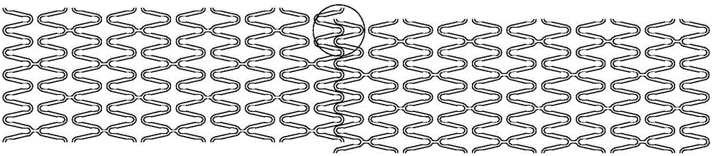
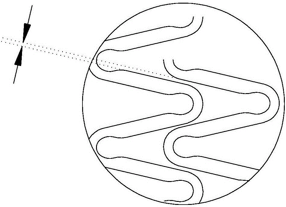
[0027] Such as figure 1 As shown, the first graphic and the second graphic are spliced end to end according to the dislocation method, and the minimum distance between the first graphic and the second graphic is guaranteed to be 0.020mm, that is, the process of 0.020mm is reserved margin. figure 2 The process margin part is enlarged and displayed, and the width between the two arrows is the process margin.
[0028] Generate the NC program on the host device for the two identical graphics after misalignment, and cut the process margin part of the bracket pipe with a laser cutting machine to separate the two bracket pipes. Use this method for figure 1 The length of the bracket pipe used for cutting the two graphic brackets in the middle is much smaller than the length of the tube used to cut the two graphic brackets one by one according to the traditional method, and it reduces the need to move 2mm more towards the cuttin...
Embodiment 2
[0029] Embodiment 2: Three identical graphics splicing
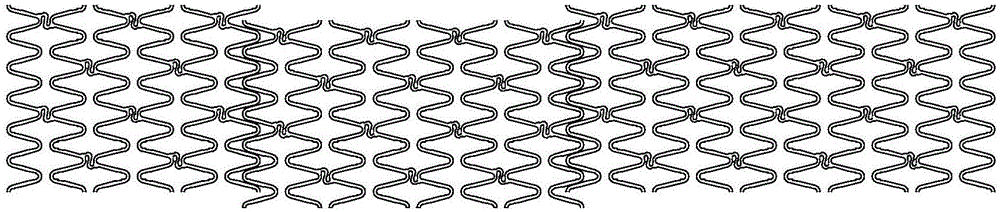
[0030] Such as image 3 As shown, after splicing the first figure and the second figure end-to-end according to the dislocation arrangement method, then place the tail end of the second figure and the head end of the third figure in dislocation; make each figure The minimum distance between them is 0.020mm, that is, a process margin of 0.020mm is reserved.
[0031] Generate the NC program on the host device for the three misplaced graphics, and cut the process margin of the bracket pipe with a laser cutting machine to separate the three bracket pipes. Use this method for image 3 The length of the bracket pipe used for cutting the three graphic brackets in the middle is much smaller than the length of the tube used for cutting the three graphic brackets one by one according to the traditional method, and it reduces the need to move 4mm to the direction of the cutting machine when cutting alone. To the amount, so as to...
Embodiment 3
[0032] Embodiment 3: Two different graphics splicing
[0033] Such as Figure 4 As shown, two different graphics are spliced end to end according to the dislocation method, and the minimum distance between the first graphic and the second graphic is guaranteed to be 0.020mm, that is, a process margin of 0.020mm is reserved.
[0034] Generate the NC program on the host device for the two different graphics after misalignment, and cut the process margin part of the bracket pipe with a laser cutting machine to separate the two bracket pipes. Use this method for Figure 4 The length of the bracket pipe used for cutting the two graphic brackets in the middle is much smaller than the length of the tube used to cut the two graphic brackets one by one according to the traditional method, and it reduces the need to move 2mm more towards the cutting machine when cutting alone. To the amount, so as to achieve the purpose of saving pipes. At the same time, cutting these two graphics ...
PUM
 Abstract
Description
Claims
Application Information
 - R&D
- Intellectual Property
- Life Sciences
- Materials
- Tech Scout
- Unparalleled Data Quality
- Higher Quality Content
- 60% Fewer Hallucinations
Browse by: Latest US Patents, China's latest patents, Technical Efficacy Thesaurus, Application Domain, Technology Topic, Popular Technical Reports.
© 2025 PatSnap. All rights reserved.Legal|Privacy policy|Modern Slavery Act Transparency Statement|Sitemap|About US| Contact US: help@patsnap.com