Manufacturing method of metal hollow microsphere

A technology of hollow microspheres and manufacturing methods, applied in the field of metal hollow microspheres, can solve problems such as difficulty in ensuring material density, compactness, and affecting the performance of metal hollow microspheres, and achieve the effect of ensuring the composition

Inactive Publication Date: 2017-06-13
LASER FUSION RES CENT CHINA ACAD OF ENG PHYSICS
View PDF6 Cites 1 Cited by
  • Summary
  • Abstract
  • Description
  • Claims
  • Application Information

AI Technical Summary

Problems solved by technology

The preparation of inertial confinement fusion metal target pellets (metal hollow microspheres) generally adopts coating methods such as magnetron sputtering on the surface of the mold core ball made of organic materials, and then degrades the mold core through high temperature to obtain hollow metal microspheres. It is difficult to ensure the density and compactness of the material, which will affect the performance of metal hollow microspheres

Method used


Image

  • Manufacturing method of metal hollow microsphere
  • Manufacturing method of metal hollow microsphere
  • Manufacturing method of metal hollow microsphere

Examples


Embodiment 1

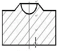
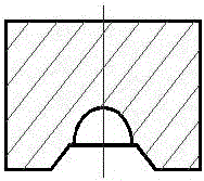
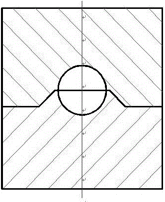
[0030] Fig. 1 is a schematic diagram of the interface structure in the present invention, wherein, Figure 1a , Figure 1b Respectively, the schematic diagram of the interface structure of Yin and Yang, figure 2 It is a schematic diagram of the sample after diffusion bonding in the present invention, image 3 It is a schematic diagram of the sample after processing the first outer hemisphere in the present invention, Figure 4 It is a sample schematic diagram of the first outer hemispherical surface processed by vacuum adsorption clamping in the present invention, Figure 5 Schematic diagram of the structure of hollow metal microspheres processed for the present invention. In Figure 1 to Figure 5 Metallic hollow microspheres with an outer diameter of Ø2.0mm and a wall thickness of 200µm were manufactured in China. The material of metal hollow microspheres is copper, and its manufacturing process is as follows:

[0031] a. Diamond turning is used to process the inner he...

Embodiment 2

[0045] Fabricate metal hollow microspheres with an outer diameter of Ø10.0mm and a wall thickness of 150µm. The material of metal hollow microspheres is copper, and its manufacturing process is as follows:

[0046] The method in this embodiment is the same as in embodiment 1, the difference is

[0047] In the step a, the inner hemispherical machining tool geometric parameters: rake angle gamma 0 = 0°, relief angle α 0 6°, leading angle kappa r is 95°, the secondary deflection angle κ' r is 50°, the radius of the tool nose arc r ε is 2µm.


PUM

PropertyMeasurementUnit
Circularityaaaaaaaaaa
thicknessaaaaaaaaaa

Abstract

The invention provides a manufacturing method of a metal hollow microsphere. The manufacturing method is characterized in that a diamond tool is used to machine inner semispherical faces and an interface on the end face of a metal bar, each inner semispherical face is polished into a mirror face through the inner semispherical face grinding technology, using material diffusion to connect the two inner semispherical faces under a vacuum, high-temperature and high-pressure environment, using the diamond turning technology to machine a first outer semispherical face, using a clamp special for the outer semispherical face to clamp and machine a second outer semispherical face, using the four-axis sphere grinding technology to grind the whole outer spherical face, using CT to detect the wall thickness and the wall thickness evenness of the sphere, performing correction until the wall thickness and the wall thickness evenness satisfy requirements, and polishing into mirror faces to obtain the metal hollow microsphere. The manufacturing method has the advantages that the outer diameter phi of the metal hollow microsphere manufactured by the method is 1-10mm, and the wall thickness of the metal hollow microsphere is 100-200 micrometers; the machining of the inner semispherical faces of the metal hollow microsphere is achieved; automatic centering of the connection of the two inner semispherical faces is achieved; connection of two semispherical faces is achieved, and component consistency of the metal hollow microsphere is guaranteed.

Description

technical field [0001] The invention belongs to the field of ultra-precision micromachining, and in particular relates to a method for manufacturing metal hollow microspheres. Background technique [0002] Precision spheres are important components in roundness meters, gyroscopes, bearings, and precision measuring instruments. In the electrostatic gyroscope, the hollow spherical rotor is the core component of the electrostatic gyroscope. Its quality and precision are important factors that directly affect the overall accuracy of the electrostatic gyroscope (positioning accuracy and navigation accuracy). In the state, it can guarantee a small sphericity error and mass imbalance, the sphericity error is below 0.05μm, and the surface roughness is below 25nm; in measuring equipment such as roundness meters, precision spheres are often used as the benchmark for precision measurement; In inertial confinement fusion research, hollow microspheres (target pellets) are the core compo...

Claims


Application Information

Patent Timeline
Patent Type & Authority Applications(China)
IPC IPC(8): B23P13/02
CPCB23P13/02
Inventor 谢军蒋柏斌黄燕华杜凯何智兵李国张海军宋成伟杨蒙生魏胜袁光辉高莎莎初巧妹童维超张昭瑞李朝阳易泰民杨洪
Owner LASER FUSION RES CENT CHINA ACAD OF ENG PHYSICS
Why Eureka
Try Eureka