Multi-travel-device vehicle and multi-rail traffic facility

A driving device and vehicle technology, which is applied in the field of manufacturing engineering, vacuum pipeline facility construction engineering, and transportation facility construction engineering, and can solve problems such as occupancy, many accidents, and waste of vehicle resources

Inactive Publication Date: 2017-06-13
吕怀民
View PDF0 Cites 8 Cited by
  • Summary
  • Abstract
  • Description
  • Claims
  • Application Information

AI Technical Summary

Problems solved by technology

[0003] Because there are too many types of existing traffic vehicles and means of transportation, and because there are too many types of existing traffic line facilities, each of them goes their own way, causing many problems as follows: 1. Occupy and waste a large amount of traffic line space
2. Occupying and wasting a lot of vehicle resources, power energy, and urban space resources
3. Occupying and wasting a lot of passenger transfer time
4. Since the means of transportation cannot be "fully tracked", and because the road vehicles do not drive on the line with the exclusive right of way, the speed is slow and there are many accidents, and it is impossible to truly realize unmanned driving (full automatic driving)
5. Duplication of investment in transportation vehicles and traffic line facilities, resulting in a large waste of investment
6. The cost of "full transportation" for passenger travel is high
6. Since the means of transportation cannot be "fully electrified", the air pollution and visual pollution caused by ordinary cars in the city have been greatly increased

Method used


Image

  • Multi-travel-device vehicle and multi-rail traffic facility
  • Multi-travel-device vehicle and multi-rail traffic facility
  • Multi-travel-device vehicle and multi-rail traffic facility

Examples


Embodiment 1

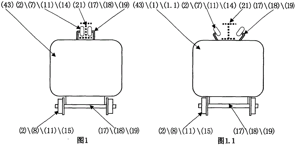
[0123] Example 1. From Fig. 1, Fig. 1.1, Fig. 6, Fig. 6.1, it can be seen that the upper rail traveling device (7) of the single-track road bench system (14) and the lower rail traveling device (8) of the double-rail road bench system (15) are both An electric locomotive (42) adopting multiple traveling devices of a rail-wheel traveling device (11).

[0124] The vehicle of this kind of multiple driving devices is an electric motor vehicle (42), which includes a load body part (1), a running part (2), a control part (4), and a driving part (5);

[0125] Its driving part (5) or control part (4) is set in the following two positions, the load part (1) and the driving part (2);

[0126] The drive part (5) includes an electric drive system (5.1); the electric drive system (5.1) is connected to the driving part (2) by power and circuit connections, and the electric drive system (5.1) drives the running part (2) to travel:

[0127]It is characterized in that: its driving part (2) i...

Embodiment 2

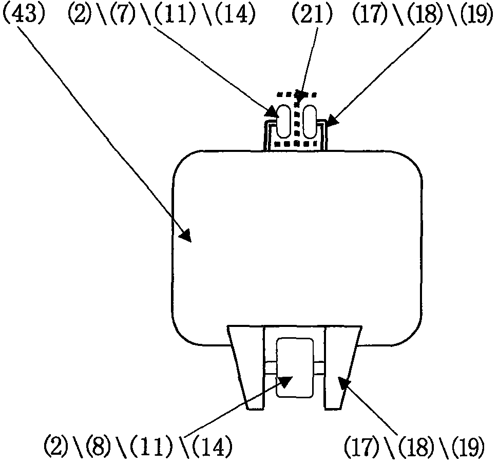
[0136] Example 2. From figure 2 , Figure 2.1 It can be seen that it is the electric train (43) of the multiple traveling devices of the rail wheel traveling device (11) that are provided with the upper rail traveling device (7) and the lower rail traveling device (8) of the monorail platform system (14).

[0137] It is characterized in that: the rail wheel traveling device (11) of its lower rail traveling device (8) travels on the monorail line (21); its traveling platform system (17) includes the following wheel group structure and single wheel frame structure; All the other features are the same as in Example 1.

[0138] This electric train (43) is exactly common straddle type monorail aerial train. The multifunctional rail vehicle can run on the existing aerial suspension monorail (21) or on the existing straddle monorail (21).

Embodiment 3

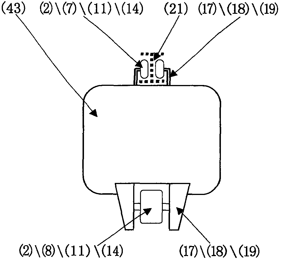
[0139] Example 3. From image 3 , Figure 3.1 As can be seen, it is the electric train (43) that the upper track running device (7) and the side track running device (9) of the monorail platform system (14) all adopt the multiple running devices of the rail wheel running device (11).

[0140] It is characterized in that: it is provided with a side rail running device (9), and the side rail running device (9) is arranged on two sides of the load body part (1) and can be connected with the load body part (1); its monorail road platform The upper rail traveling device (7) and the side rail traveling device (9) of the frame system (14) all adopt the rail wheel traveling device (11), and the rail wheel traveling device (11) travels on the monorail line (21); (17) includes the following wheel set structure, single wheel frame structure; image 3 The rail wheel traveling device (11) in presents vertically, in Figure 3.1 The rail wheel traveling device (11) in presents lateral di...


PUM


Abstract

The invention relates to the technical field of vehicle and traffic facility engineering, in particular to a multi-travel-device vehicle, characterized in that a travel portion (2) includes at least two types of upper rail travel devices (7), lower rail travel devices (8), side rail travel devices (9), and road travel devices (10), or wheeltrack travel devices (11), maglev travel devices (12) and air-suspended travel devices (13), or at least two types of single-rail rack system (14), a double-rail rack system (15) and a multi-rail rack system (16); a multi-rail traffic facility is characterized in that a rail line (20) includes at least two types of a single-rail line (21), a double-rail line (22), a multi-rail line (23), or at least two types of an upper rail line (24), a lower rail line (25) and side rail lines (26), or at least two types of wheel rail lines (27), maglev rail lines (28), air-suspended rail lines (29), and conveyer belt surface rail lines (30). The multi-travel-device vehicle and the multi-rail traffic facility allow one vehicle to be multifunctional and one line to be multifunctional; vehicles, traffic facilities, and the cost and time consumption for 'whole trip range' are greatly reduced.

Description

technical field [0001] The present invention relates to the technical field of traffic engineering, manufacturing engineering of vehicles, and construction engineering of traffic facilities, especially electric traction or running platform, motor vehicle, train, aircraft, ship manufacturing engineering, rail line facilities, and vacuum pipeline facility construction engineering technical field. Background technique [0002] Existing traffic vehicles include rail vehicles and road vehicles. Existing rail vehicles include lower rail vehicles (its wheels are arranged on the top of the carriage), and upper rail vehicles (its wheels are arranged on the top of the carriage). Existing rail vehicles also include monorail vehicles (its wheels are arranged on a single track), rail vehicles (its wheels are arranged on 2 tracks). Existing rail vehicles also include magnetic levitation vehicles (its carriage is suspended on the track by magnetic force), and air suspension vehicle (its ...

Claims


Application Information

Patent Timeline
Patent Type & Authority Applications(China)
IPC IPC(8): B61B13/00B61B13/04B61B13/08B61B13/10B60L9/00B60M1/13
CPCB60L9/00B60L2200/10B60L2200/24B60L2200/26B60L2200/32B60M1/13B61B13/00B61B13/04B61B13/08B61B13/10Y02T30/00
Inventor 吕怀民
Owner 吕怀民
Why Eureka
Try Eureka