Anchor drilling machine independent rack for machine

A technology for bolting rigs and racks, which is used in the installation of bolts, drilling equipment, earth-moving drilling, etc., can solve the problems of strong shock and vibration, inoperability, damage to the bolting machine, etc., and achieves increased strength and rigidity. Compact structure Effects of design, enhanced stability and reliability

Inactive Publication Date: 2017-06-13
沈阳重机重矿机械设备制造有限公司
View PDF12 Cites 12 Cited by
  • Summary
  • Abstract
  • Description
  • Claims
  • Application Information

AI Technical Summary

Problems solved by technology

But because this utility model installs the bolter on the side of the cutting part of the roadheader to realize the integrated structure of the bolter and the cutting part of the roadheader, this structure has brought the following problems: one is to install the anchor The installation of the rod machine on the side of the cutting part of the roadheader affects the working range of the cutting part of the roadheader, and also affects the operator's line of sight when cutting; Strong, it will seriously affect the safe service life of the bolter; the third is that when the cutting part is cutting, there will be a large amount of mineral fragments and dust or piles on the cutting part when the roof falls, which will cause the bolter The fourth is that when the utility model needs the work of the bolter, the bolter needs to rely on the lifting and swinging of the cutting part and the function of the bolter itself to complete the anchoring work of the roadway bolt. Safety production has formulated a ser...

Method used


Image

  • Anchor drilling machine independent rack for machine
  • Anchor drilling machine independent rack for machine
  • Anchor drilling machine independent rack for machine

Examples


Embodiment Construction

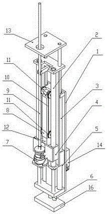
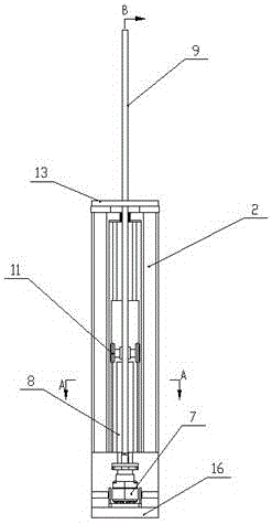
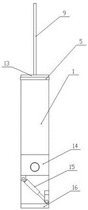
[0037]As shown in the drawings, the technical solution adopted by the present invention includes a drilling rig frame 1, on which a sliding guide rail 5, a first guide post oil cylinder 3, a side swing bracket 14 and a side swing oil cylinder 15 are installed. The second guide post oil cylinder 2, the drilling rig sliding bracket 4 and the drilling rig oil cylinder 12 are installed on the 5, and the bolt drill 7 is installed on the drilling rig sliding bracket 4. The sliding guide rail 5 is composed of a perforated upper cover 5-1, a back plate 5-2, bottom plate 5-3 and perforated slider 5-4, the second guide post oil cylinder 2 is installed between the perforated upper cover plate 5-1 and the bottom plate 5-3, and the piston of the second guide post oil cylinder 2 The rod is fixedly connected to the bottom plate of the drilling rig frame 1, the slide block 5-4 with holes slides on the cylinder block of the first guide column oil cylinder 3, and the upper cover plate 5-1 with h...


PUM


Abstract

The independent frame of the mechanical rock bolter overcomes the problem that the existing drilling rig frame has a complex structure and a large volume, and is limited by the width of the roadway and the height of the roof of the roadway, and it is difficult to arrange multiple frames. The sliding guide rail, the first guide post oil cylinder and the second guide post oil cylinder form a two-stage sliding guide rail. The drilling rig sliding bracket, the drilling rig oil cylinder, the top plate and the bottom plate support oil cylinder, and the swing side swing oil cylinder and bracket are also installed on the drilling rig frame, which is beneficial The effect is that the sliding guide column cylinder and its piston rod play multiple roles of cylinder, guide rail and mutual support. The structure is compact and ensures the strength and rigidity of the entire frame. The drilling rig sliding bracket is located at the bottom of the drilling rig bracket. The secondary sliding makes The shorter drilling rig has a large stroke and also has the function of temporary support, which enhances the safety and stability of the anchor protection work. The compact structure design enables multi-frame installation when realizing the integration of digging and anchoring On fully mechanized excavator or continuous miner.

Description

technical field [0001] The invention belongs to the technical field of tunneling and supporting in coal mine roadways, and in particular relates to an independent machine frame of a bolter drilling machine used for an integrated mechanized excavation machine and a continuous mining machine. Background technique [0002] In the prior art, the support work of the roadheader after the roadway is excavated is a difficult, complicated and extremely inefficient work. The main reason is that the split work of the roadheader and the bolter causes a lot of waste of time, and the effective working time The ratio is very small; manual bolting is not only labor-intensive, but also requires a large number of personnel, so the efficiency is very low. Therefore, there is a great need for an airborne bolter that can be quickly carried out during or immediately after the excavation of the roadheader. The bolt support work can improve the working efficiency of the roadheader, reduce the labor...

Claims


Application Information

Patent Timeline
IPC IPC(8): E21B15/00E21D20/00
CPCE21B15/003E21D20/003
Inventor 元钢蔺任志包宏马影刘玉凤元靖云苏金玲赵飞张国新李本学王红宇
Owner 沈阳重机重矿机械设备制造有限公司
Why Eureka
Try Eureka