
A high-speed train brake disc and its preparation method and application

A technology of high-speed trains and brake discs, applied in the direction of brake discs, brake types, brake components, etc., can solve problems such as poor thermal conductivity and thermal conductivity, poor heat dissipation, damage, etc.

Active Publication Date: 2019-02-05
HUNAN SHIXIN NEW MATERIALS CO LTD
View PDF7 Cites 1 Cited by
  • Summary
  • Abstract
  • Description
  • Claims
  • Application Information

AI Technical Summary

Problems solved by technology

Due to the poor thermal conductivity and thermal conductivity of the steel back, the heat dissipation effect is not good, so that after the brake disc is heated by friction, it will cause ablation of the contact friction surface, and the thermal stress generated by the interaction of the friction pairs will also cause the brake disc to burn. Thermal Creep and Thermal Fatigue Damage
Moreover, the high density of the steel back limits the further improvement of the train speed and leads to an increase in the energy consumption of the train

Method used


Image

  • A high-speed train brake disc and its preparation method and application
  • A high-speed train brake disc and its preparation method and application
  • A high-speed train brake disc and its preparation method and application

Examples


Embodiment 1

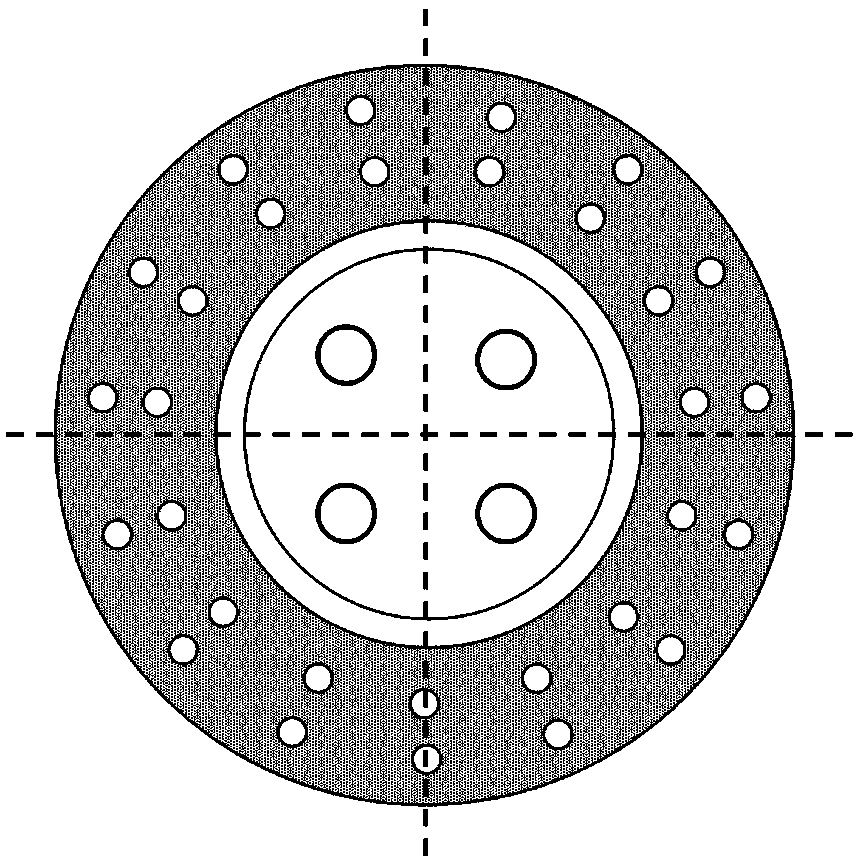
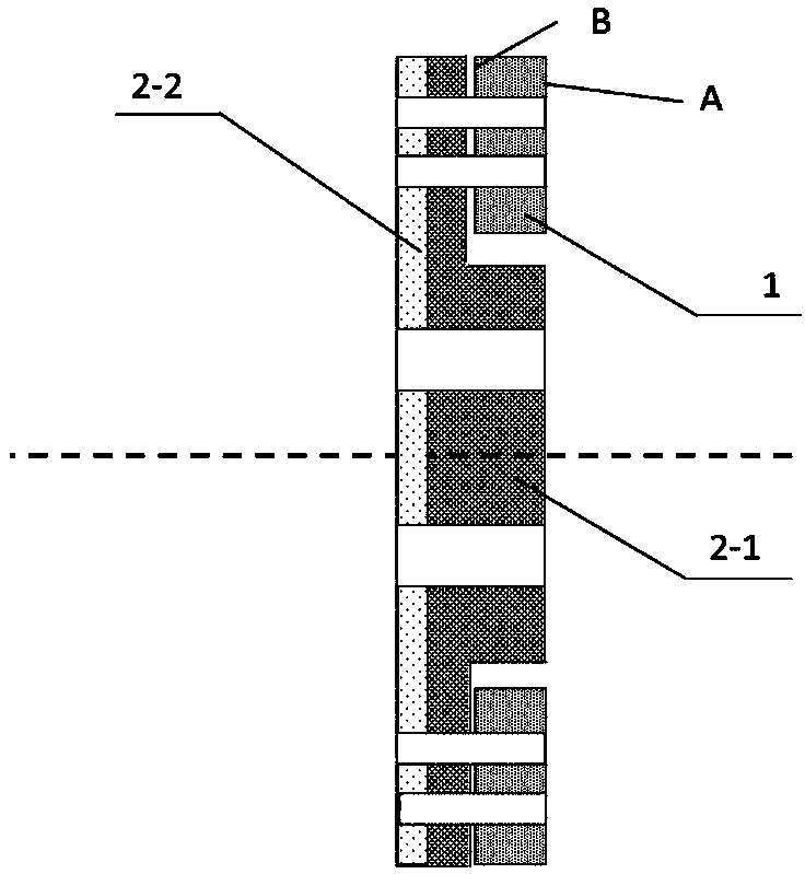
[0165] Referring to Figures 2 to 4, the brake disc of this new type of high-speed train includes a carbon ceramic friction disc 1 and a composite double-layer metal skeleton 2; the carbon ceramic friction disc 1 includes several counterbores 3. The composite double-layer metal skeleton 2 is composed of a copper-based alloy disk 2-1 and an aluminum-based alloy disk 2-2; the composite double-layer metal skeleton 2 also includes counterbore holes 3 at several positions and the carbon ceramic friction disk 1 The corresponding counterbore 4 and middle hole 5; the carbon-ceramic friction disc 1 and the composite double-layer metal skeleton 2 are cold riveted and connected in sequence with copper or steel rivets, the riveting force is 0.7-1MPa, and the carbon-ceramic The non-friction surface B of the friction disc 1 corresponds to the disc surface C of the copper-based alloy disc 2-1. When in use, the present invention is connected with the train wheel hub through the middle hole 6 o...

Embodiment 2

[0219] Referring to Figures 2 to 4, the brake disc of this new type of high-speed train includes a carbon ceramic friction disc 1 and a composite double-layer metal skeleton 2; the carbon ceramic friction disc 1 includes several counterbores 3. The composite double-layer metal skeleton 2 is composed of a copper-based alloy disk 2-1 and an aluminum-based alloy disk 2-2; the composite double-layer metal skeleton 2 also includes counterbore holes 3 at several positions and the carbon ceramic friction disk 1 The corresponding counterbore 4 and middle hole 5; the carbon-ceramic friction disc 1 and the composite double-layer metal skeleton 2 are cold riveted and connected in sequence with copper or steel rivets, the riveting force is 0.7-1MPa, and the carbon-ceramic The non-friction surface B of the friction disc 1 corresponds to the disc surface C of the copper-based alloy disc 2-1. When in use, the present invention is connected with the train wheel hub through the middle hole 6 o...


PUM

PropertyMeasurementUnit
densityaaaaaaaaaa
densityaaaaaaaaaa
particle sizeaaaaaaaaaa

Abstract

The invention relates to a high speed train brake disk, a preparation method and an application thereof, and belongs to the technical field of development of a special brake disk. The high speed train brake disk comprises a frictional disk (1) and a composite double-layered metal framework (2); the frictional disk (1) is made of carbon / ceramic composite material, and the composite double-layered metal framework (2) is made of double-layered metal material compounded by hot-pressing. The combined brake disk comprises the carbon / ceramic frictional disk (1) and the composite double-layered metal framework (2); through riveting, the carbon / ceramic frictional disk (1) and the composite double-layered metal framework (2) are connected into one. The brake disk designed in the invention can be applied to the high speed train, the service life thereof is obviously longer than that of the existed product.

Description

technical field [0001] The invention relates to a high-speed train brake disc, a preparation method and application thereof, and belongs to the technical field of special brake disc development. Background technique [0002] The brake disc of a high-speed train is one of the most critical components in the brake device. As the speed of the train increases and the operating conditions of the brake are severe, the huge thermal load and thermal shock of the brake will produce a large temperature gradient, resulting in the formation of a huge thermal stress in the brake disc. Therefore, it is required that the brake disc material not only has stable and uniform friction performance and high wear resistance, but also must have high thermal fatigue performance and thermal conductivity, low elastic modulus and thermal expansion coefficient, so that braking The heat can be dissipated quickly to reduce the high thermal stress caused by the rapid cooling and heating of the friction s...

Claims


Application Information

Patent Timeline
Patent Type & Authority Patents(China)
IPC IPC(8): F16D65/12F16D69/02C22C9/00C22C9/06C22C9/01C22C9/10C22C32/00C22C21/10C22F1/08C22F1/053C23C16/26
CPCC22C9/00C22C9/01C22C9/06C22C9/10C22C21/10C22C32/0021C22C32/0063C22F1/053C22F1/08C23C16/26F16D65/127F16D69/023F16D2200/0047
Inventor 李鹏涛
Owner HUNAN SHIXIN NEW MATERIALS CO LTD
Learn More