Multifunctional splitting snap-chilling heat exchanger

A quenching heat exchanger, multi-functional technology, applied in the direction of heat exchanger type, heat exchanger shell, indirect heat exchanger, etc., can solve the problem of increasing equipment cost, reducing equipment utilization, and not being able to simultaneously crack liquid phase raw materials and Gas raw materials and other issues

Pending Publication Date: 2017-06-13
NANJING TIANHUA CHEM ENG +1
View PDF7 Cites 3 Cited by
  • Summary
  • Abstract
  • Description
  • Claims
  • Application Information

AI Technical Summary

Problems solved by technology

[0004] Due to the different components in the cracking raw materials, the cracking liquid phase raw materials are more likely to coke than the cracking gas raw materials. To reduce the coking tendency of the quenching heat exchanger, it is necessary to control the outlet temperature of the cracking gas so that the outlet temperature should be higher than the dew point of the cracking gas. For example, when cracking light raw material naphtha, the dew point of the cracked gas is about 350°C, which requires that the outlet temperature of the quenching heat exchanger should be higher than 350°C, and for the cracked gas raw material, the dew point of the cracked gas is lower, and If the temperature is lower than the saturated water vapor temperature of the cooling medium (about 330°C), it is necessary to adopt multi-stage quenching technology or use a lower temperature cooling medium. Since the dew point of the pyrolysis gas after the cracking of the liquid phase raw material and the gas raw material is different, the corresponding quenching The outlet temperature of the heat exchanger is also different. The quenching heat exchanger of the prior art can only realize the quenching of a single liquid-phase raw material or a single gas raw material, and cannot simultaneously crack the liquid-phase raw material and the gas raw material, which will inevitably reduce the utilization rate of the equipment. , thereby increasing equipment costs and reducing economic benefits

Method used


Image

  • Multifunctional splitting snap-chilling heat exchanger
  • Multifunctional splitting snap-chilling heat exchanger
  • Multifunctional splitting snap-chilling heat exchanger

Examples


Embodiment Construction

[0035] The present invention will be described in detail below in conjunction with specific embodiments and accompanying drawings.

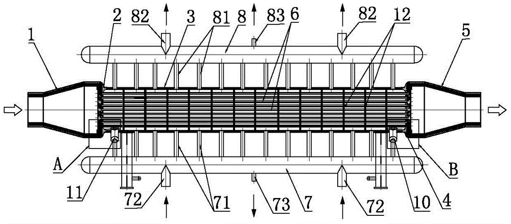
[0036] A kind of multifunctional pyrolysis quenching heat exchanger of the present embodiment, as figure 1 As shown, its structure includes the inlet tube box 1, the inlet flexible tube plate 2, the shell 3, the outlet flexible tube plate 4 and the outlet tube box 5 connected in sequence, and the shell 3 is built with the inlet tube box 1 and the outlet tube The heat exchange tube 6 of case 5, the cracking raw material enters from the inlet tube box 1 and exchanges heat with the cooling medium in the heat exchange tube 6 and the housing 3, and then flows out through the outlet tube box 5 (such as figure 1 indicated by the middle arrow), where the cracking raw materials include high-temperature liquid-phase raw materials or high-temperature gas raw materials.

[0037] Such as figure 1 As shown, the quench heat exchanger also includes a downcomer...


PUM


Abstract

The invention discloses a multifunctional splitting snap-chilling heat exchanger which structurally comprises a shell. The shell communicates with a descending pipe header and an ascending pipe header. A boiler water supply inlet is formed in one end of the shell, and a boiler water supply outlet is formed in the other end of the shell. In the splitting process of a liquid-phase raw material, the boiler water supply inlet and the boiler water supply outlet are closed, an inlet of the descending pipe header and an outlet of the ascending pipe header are opened, a cooling medium enters the shell through the descending pipe header and is subjected to heat exchange with a heat exchange tube and then is discharged through the ascending pipe header, and accordingly snap chilling of the liquid-phase raw material can be achieved. In the splitting process of a gas-phase raw material, the inlet of the descending pipe header and the outlet of the ascending pipe header are closed, the closed boiler water supply inlet and the boiler water supply outlet are opened, the cooling medium enters the shell through the boiler water supply inlet and is subjected to heat exchange with the heat exchange tube and then is discharged through the boiler water supply outlet, and accordingly snap chilling of the gas-phase raw material can be achieved. The multifunctional splitting snap-chilling heat exchanger can achieve snap chilling of the liquid-phase raw material and the gas-phase raw material at the same time, and thus the equipment utilization rate can be increased obviously.

Description

technical field [0001] The invention relates to the technical field of quenching heat exchangers, in particular to a multifunctional cracking quenching heat exchanger. Background technique [0002] The cracking furnace is the key unit of the ethylene plant. After the cracking raw materials are cracked at high temperature in the furnace tube of the cracking furnace, ethylene will be produced, and important by-products such as propylene, butadiene, benzene, toluene, and xylene can also be obtained. The high-temperature cracked gas (generally 750-900°C) at the outlet of the cracking furnace will continue to undergo cracking reaction (secondary reaction) under the condition of high temperature at the outlet. If the residence time is too long, the secondary reaction will increase, and the result will make the cracked product The recovery rate of olefins decreases, methane, hydrogen, and heavy tar increase, and the tendency of coking increases; if the recovery rate of olefins is t...

Claims


Application Information

Patent Timeline
Patent Type & Authority Applications(China)
IPC IPC(8): F28D7/16F28F9/02F28F9/22
CPCF28D7/16F28F9/0229F28F9/22F28F2009/222
Inventor 李金科黄嗣罗李宁柯建军孙建兵林进华
Owner NANJING TIANHUA CHEM ENG
Why Eureka
Try Eureka