Method for detecting non-cooperation pulse compression radar weak target based on wavelet denoising

A pulse compression radar and weak target technology, which is applied in radio wave measurement systems, radio wave reflection/reradiation, and measurement devices, etc., can solve the problems of echo signal spectrum aliasing and cannot be effectively removed, and achieve improved signal-to-noise Ratio, small amount of data processing, and the effect of simplifying the processing flow

Active Publication Date: 2017-06-13
NAT UNIV OF DEFENSE TECH
4 Cites 11 Cited by

AI-Extracted Technical Summary

Problems solved by technology

For pulse compression radar, the echo signal containing white noise can effectively filter out most of the noise after matched filtering, but the remaining noise is aliased ...

Method used

S6. carry out wavelet denoising processing to the peak envelope in step S5: in step S4, the remaining noise of baseband echo signal after matched filtering is mainly in-band noise, that is, the noise spectrum is concentrated in the echo signal frequency band. Due to the aliasing of the frequency spectrum of the noise and the echo signal, the distribution of the wavelet coefficients of the two will overlap, and the direct use of the wavelet denoising method to process the noisy baseband echo signal cannot achieve good results. The non-coherent accumulation based on line detection is realized by adding the amplitude energy of the signal envelope, so it is not necessary to directly denoise the noisy echo signal, but to match the peak value of the echo signal after filtering As the processing object, the envelope is used to save the main lobe of the echo signal in the peak envelope and filter out the envelope of the in-band noise through wavelet transform, and finally achieve the purpose of improving the signal-to-noise ratio of the echo signal. After the main lobe of the envelope of the echo signal is decomposed by wavelet at various scales, the energy is mainly concentrated in the low frequency part, so only the low frequency wavelet coefficients obtained by wavelet decomposition need to be thresholded, and the wavelet coefficients of other decomposition layers are set to zero, so that Therefore, the main lobe energy of the echo signal envelope after the matche...

Abstract

The invention belongs to the technical field of radar signal processing, and particularly relates to a method for detecting a non-cooperation pulse compression radar weak target based on wavelet denoising. The method is characterized in that an echo signal with noise is not directly denoised, but the matched and filtered peak envelope is used as a processed object; an envelope main lobe of the matched and filtered echo signal is remained by the wavelet denoising; after the envelope main lobe of the echo signal is decomposed by wavelets of various scales, the energy is mainly centralized at the low-frequency part, only the setting threshold value of the low-frequency wavelet coefficient after wavelet decomposing is screened, the other decomposing layers are zeroed, then the envelope main lobe of the echo signal is remained, and most of noise is filtered, so as to effectively accumulate the energy of the echo signal through Radon conversion. The method has the advantages that the influence caused by the in-band noise of the echo signal can be eliminated, the signal and noise ratio of the echo signal is improved, the linear detection method can effectively accumulate the target echo energy, the detection probability is finally improved, and the weak target is detected.

Application Domain

Technology Topic

Image

  • Method for detecting non-cooperation pulse compression radar weak target based on wavelet denoising
  • Method for detecting non-cooperation pulse compression radar weak target based on wavelet denoising
  • Method for detecting non-cooperation pulse compression radar weak target based on wavelet denoising

Examples

  • Experimental program(1)

Example Embodiment

[0034] The present invention will be further described below with reference to the accompanying drawings and specific embodiments.
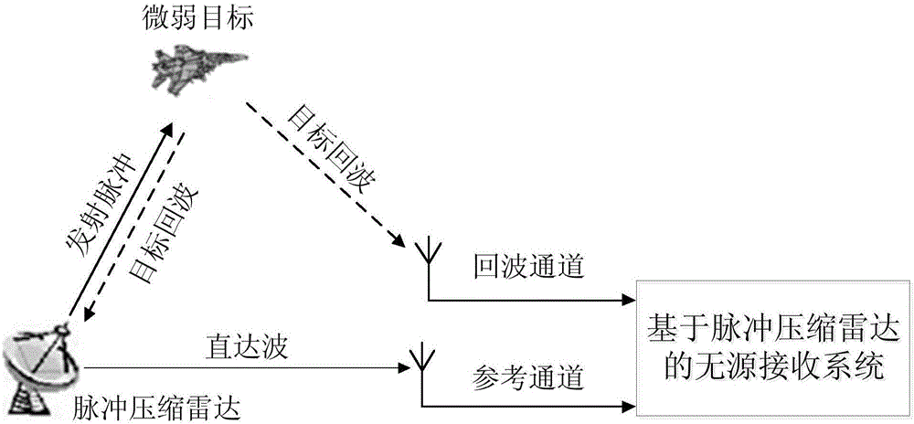
[0035] In this embodiment, a pulse compression radar is used as a non-cooperative radiation source, the radar is a pulse system, the signal modulation form is LFM, and the straight line detection method adopts Radon transform. The passive receiving system based on the pulse compression radar is divided into a reference channel and an echo channel, which are respectively used to receive the direct wave signal transmitted by the pulse compression radar and the echo signal reflected by the target. Its system composition diagram is as follows figure 1 shown.
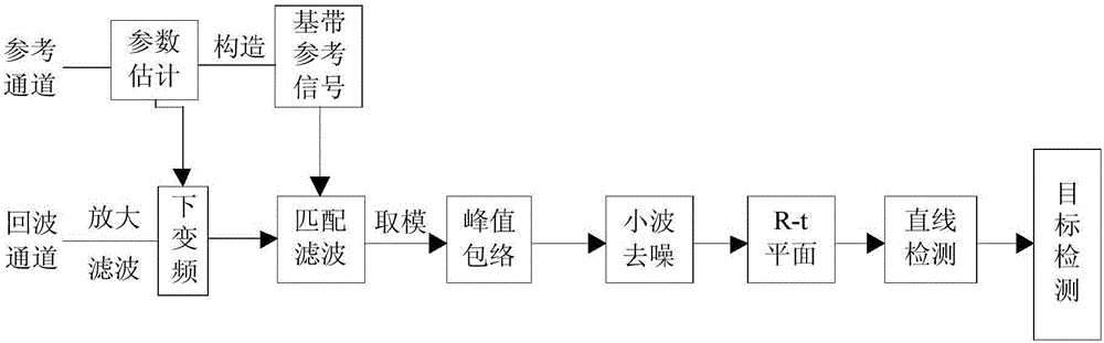
[0036] refer to figure 2 The implementation flowchart in the present invention specifically includes the following steps:
[0037] S1. The passive receiving system based on the pulse compression radar is divided into a reference channel and an echo channel. The two channels respectively collect the direct wave signal and the target echo signal emitted by the pulse compression radar in the same time period. The passive receiving system adopts the band-pass quadrature sampling to receive the signal, and the bandwidth covers the working frequency band of the pulse compression radar.
[0038] S2. Parameter estimation is performed on the direct wave signal collected by the reference channel, and the parameters include pulse width, bandwidth and carrier frequency, and the estimated parameters are used to construct a baseband reference signal;
[0039] S3. Amplify and filter the weak echo signal reflected by the target received by the echo channel, and then down-convert the echo signal according to the carrier frequency of the direct wave signal estimated in S2 to obtain a baseband echo signal;
[0040] S4. Use the baseband reference signal constructed in step S2 to perform matched filtering on the baseband echo signal obtained by down-conversion in step S3. After matched filtering, the residual in-band noise, that is, the noise is aliased with the spectrum of the echo signal. image 3The spectrogram of the baseband echo signal after matched filtering is given; from image 3 It can be seen that there is a large amount of noise interference in the spectrum after matched filtering of the echo signal, and the spectrum of the noise and the signal are mixed with each other.
[0041] S5. take the modulo of the result obtained by the matched filtering in step S4, and obtain the peak envelope after the matched filtering of the echo signal, and the peak envelope is the linear superposition of the echo signal envelope and the noise envelope; Figure 4 The matched-filtered peak envelope of an echo signal is given, and its amplitude is normalized. from Figure 4 It can be seen that the envelope of the echo signal is affected by the noise envelope and is difficult to distinguish. It is difficult to detect weak targets if the signal with such a low signal-to-noise ratio is directly used for energy accumulation.
[0042] S6. Perform wavelet denoising processing on the peak envelope in step S5: in step S4, the remaining noise of the baseband echo signal after matched filtering is mainly in-band noise, that is, the noise spectrum is concentrated in the echo signal frequency band. Due to the spectral aliasing of noise and echo signals, the wavelet coefficient distributions of the two will overlap. Directly using wavelet denoising methods to process noisy baseband echo signals cannot achieve good results. The non-coherent accumulation based on line detection is realized by adding the amplitude energy of the signal envelope, so it is not necessary to directly de-noise the noisy echo signal, but use the echo signal to match the filtered peak value. The envelope is the processing object. The main lobe of the echo signal in the peak envelope is saved by wavelet transform and the envelope of the in-band noise is filtered out, and finally the purpose of improving the signal-to-noise ratio of the echo signal is achieved. After the main lobe of the envelope of the echo signal is decomposed by the wavelet of each scale, the energy is mainly concentrated in the low-frequency part, so only the low-frequency wavelet coefficients obtained by the wavelet decomposition need to be thresholded, and the wavelet coefficients of other decomposition layers are set to zero, so that The main lobe energy of the echo signal envelope after matched filtering can be retained, and most of the noise energy can be removed. Finally, through inverse wavelet reconstruction, the denoised peak envelope is obtained;
[0043] combine Figure 5 , the specific implementation process of this step includes the following steps:
[0044] S6.1 performs wavelet decomposition on the peak envelope in S4, in which the coiflet 5 wavelet is selected as the wavelet base function, and the number of wavelet decomposition layers is set to three. After the peak envelope is decomposed by three layers of wavelet, three different wavelet coefficients will be obtained, but most of the main lobe energy of the echo signal envelope is concentrated in the low frequency wavelet coefficients of the third layer.
[0045] S6.2 processes the wavelet coefficients obtained in step S6.1; since the echo signal envelope is processed in step S6.1, most of its energy is concentrated in the low-frequency part of the third layer, so it is necessary to analyze the wavelet coefficients in the wavelet coefficients. The low-frequency wavelet coefficients are thresholded to preserve the energy of the echo signal. There are two kinds of commonly used wavelet thresholds: hard threshold and soft threshold. Since the soft threshold can ensure that the denoised signal is smooth and does not generate additional oscillation, the present invention selects the soft threshold for processing. The soft threshold processing compares the low-frequency wavelet coefficient with the threshold, and the point greater than the threshold becomes the difference between the point value and the threshold, and the point less than or equal to the threshold is set to zero; at the same time, since other decomposition layers are mostly noise energy, the The wavelet coefficients of other decomposition layers are set to zero. Since only the low-frequency wavelet coefficients of the third layer need to be soft-thresholded, and the wavelet coefficients of other decomposition layers are set to zero, the processing process is simplified and the amount of data to be processed is reduced.
[0046] The threshold function expression of soft threshold is:
[0047]
[0048] where sgn is the symbolic function, w k represents the wavelet coefficients of the kth layer, represents the soft threshold function corresponding to the wavelet coefficients of the kth layer, and λ represents the threshold. Since only the low-frequency wavelet coefficients after wavelet decomposition need to be soft-thresholded, the optimal threshold obtained under the limit of maximum and minimum estimation is selected, and its expression is:
[0049]
[0050] where N is the length of the peak envelope, and σ represents the standard deviation of the noise, which can usually be approximated by the standard deviation of the low-frequency wavelet coefficients.
[0051] S6.3 reconstructs the wavelet coefficients processed in step S6.2 to obtain a denoised peak envelope. Among them, the wavelet base in the wavelet reconstruction must be the same as the wavelet base used in the wavelet decomposition in step 6.1, that is, both are coiflet 5 wavelets, and the number of reconstruction layers is also 3 layers.
[0052] To illustrate the effect of wavelet denoising, Figure 4 The effect of the mid-peak envelope after wavelet denoising is as follows: Image 6 shown. from Image 6 It can be seen that after the de-noising process in step S6, the envelope main lobe of the echo signal is preserved and the noise envelope is basically filtered, that is, the signal-to-noise ratio of the echo signal is improved.
[0053] S7. Store the denoised peak envelope in step S6 in the fast-slow time domain matrix, where the fast time represents the distance R, and the slow time t corresponds to the number of pulses processed in the acquisition time period. Finally get an R-t plane, such as Figure 7 shown;
[0054] S8. utilize the R-t plane obtained in step S7 to carry out straight line detection, select Radon transformation in this specific embodiment, carry out energy accumulation to the target track; Because in the accumulation time, the motion state of the target can be approximated as uniform linear motion, utilize Radon transformation The peak envelope amplitudes of the linear trajectory of the target echo in the R-t plane can be summed and accumulated. Figure 8 The accumulation result of the R-t plane after Radon transformation is given;
[0055] S9. Use CFAR detection on the R-t plane obtained through energy accumulation in step S8, so as to complete the detection of weak targets. Figure 9 Two algorithms under different SNRs, namely the present invention and the direct use of Radon-based TBD algorithm without wavelet denoising, are given respectively to detect the probability of the target. The horizontal axis is the signal-to-noise ratio, and the vertical axis is the detection probability. Figure 9 It can be seen from the curve in the present invention that the detection probability of the target can be significantly improved.
[0056] It can be seen from the results of this embodiment that after the echo signal of the pulse compression radar is matched and filtered, the spectrum of the noise and the echo signal are aliased, which brings great difficulty to denoising and affects the detection of weak targets. detection. The invention does not directly denoise the noisy echo signal, but takes the peak envelope after matched filtering as the processing object, and retains the envelope main lobe of the matched filtered echo signal through wavelet denoising. After the main lobe of the echo signal envelope is decomposed by wavelets at various scales, the energy is mainly concentrated in the low-frequency part. In this way, it is only necessary to set thresholds for the low-frequency wavelet coefficients after wavelet decomposition, and set other decomposition layers to zero. Retaining the main lobe of the echo signal envelope and filtering out most of the noise ensures that the Radon transform can effectively accumulate the energy of the echo signal and improve the detection probability of weak targets.

PUM

no PUM

Description & Claims & Application Information

We can also present the details of the Description, Claims and Application information to help users get a comprehensive understanding of the technical details of the patent, such as background art, summary of invention, brief description of drawings, description of embodiments, and other original content. On the other hand, users can also determine the specific scope of protection of the technology through the list of claims; as well as understand the changes in the life cycle of the technology with the presentation of the patent timeline. Login to view more.

Similar technology patents

Multi-wavelength Brillouin optical time domain analyzer

InactiveCN103115632AIncrease total optical powerImprove signal-to-noise ratioSpecial purpose recording/indication apparatusOptical pathSignal-to-noise ratio (imaging)
Owner:NANJING UNIVERSTIY SUZHOU HIGH TECH INST +1

Classification and recommendation of technical efficacy words

  • Improve signal-to-noise ratio
  • Improve the probability of detection

Magnetic tape, its cleaning method, and optical servotrack forming/cleaning apparatus

InactiveUS7803471B1Improve signal-to-noise ratioDecreasing rate of fluctuationMagnetic materials for record carriersReconditioning/cleaning record carriersReflectivityMaximum rate
Owner:FUJIFILM CORP

System for generating thermographic images using thermographic signal reconstruction

ActiveUS20050008215A1Reduce size and complexityImprove signal-to-noise ratioCharacter and pattern recognitionMaterial flaws investigationSignal reconstructionThermographic imaging
Owner:THERMAL WAVE IMAGING

Hyper-spectral imaging methods and devices

InactiveUS20050270528A1Improve signal to noise ratioSmall bandwidthRadiation pyrometrySpectrum generation using diffraction elementsSpectral imagingLight spectrum
Owner:PLAIN SIGHT SYST

Detection method for moving target of pulse compression frequency-agile radar

ActiveCN106646446AImprove the probability of detectionSimple signal processingRadio wave reradiation/reflectionMatched filterMoving speed
Owner:NAT UNIV OF DEFENSE TECH

Satellite navigation time service receiver anti-spoofing method

InactiveCN105158774AImprove the probability of detectionSimple methodSatellite radio beaconingEphemerisEnvironmental geology
Owner:STATE GRID CORP OF CHINA +2

Detection tracking integrated method based on RCS prediction information

ActiveCN105842687AImprove object detection performanceImprove the probability of detectionRadio wave reradiation/reflectionObject detectionEcho signal
Owner:XIDIAN UNIV +1
Why Eureka
Try Eureka