Optical Cavity Automatic Locking Device Based on Analog Circuit and Cavity Locking Method

An automatic locking and analog circuit technology, applied in optics, nonlinear optics, instruments, etc., can solve the problems of expensive data acquisition cards, long-time automatic locking, long locking time, etc., achieve short locking time and improve long-term stable operation Ability, low cost effect

Active Publication Date: 2019-05-17
SHANGHAI PRECILASERS TECH CO LTD
View PDF1 Cites 0 Cited by
  • Summary
  • Abstract
  • Description
  • Claims
  • Application Information

AI Technical Summary

Problems solved by technology

This type of automatic locking device can be applied to experiments such as laser spectroscopy and non-classical optical state preparation. It has the advantages of wide application range and easy logic programming, but its disadvantage is that the required data acquisition card is expensive. The experiment of optical cavity locking caused waste of resources
In addition, there is also a device based on an inertial synchronization circuit (flywheel circuit) and an automatic gain control circuit (automatic gain control circuit) to realize the automatic locking of the FP cavity [Reviewof Scientific Instruments, 76, 026101 (2005)]. The problem is that when the FP cavity It takes a long time to automatically lock when it is far away from the resonance point, and a long lock time is obviously unfavorable for long-term continuous operation experiments

Method used


Image

  • Optical Cavity Automatic Locking Device Based on Analog Circuit and Cavity Locking Method
  • Optical Cavity Automatic Locking Device Based on Analog Circuit and Cavity Locking Method
  • Optical Cavity Automatic Locking Device Based on Analog Circuit and Cavity Locking Method

Examples


Embodiment Construction

[0025] The present invention will be described in further detail below in conjunction with the embodiments of the accompanying drawings, but the protection scope of the present invention should not be limited thereto.

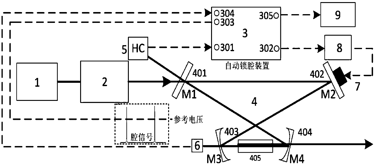
[0026] see first figure 1 , figure 1 It is a schematic structural diagram of the optical cavity automatic locking device based on the analog circuit of the present invention. It can be seen from the figure that the optical cavity automatic locking device based on the analog circuit of the present invention includes an optical system and an electronic control system:

[0027] Described optical system comprises semiconductor laser 1, fiber laser amplifier 2, ring frequency doubling cavity 4 and HC frequency discriminating optical path 5, and the composition of described ring frequency doubling cavity 4 is: along the optical path direction is input coupling mirror 401, The second cavity mirror 402, the third cavity mirror 403, the nonlinear crystal 405, the coupl...


PUM


Abstract

The invention discloses a device and a method for automatically locking an optical cavity on the basis of an analog circuit. The device is characterized by comprising an optical system and an electronic control system, wherein the optical system comprises a semiconductor laser unit, a fiber laser amplifier, an annular frequency doubling cavity and an HC (high capacity) frequency discrimination optical path; the electronic control system comprises an automatic cavity-locking device, a photoelectric detector, piezoelectric ceramics, a high voltage amplifier and an oscilloscope. According to the characteristics of optical cavity signals emerging before and after the optical cavity is locked, the annular frequency doubling cavity is automatically and quickly locked by a simple analog electronic component, and software programming and analogue-to-digital conversion processes required by a digital automatic cavity-locking device are not required, so that the device has the advantages of short locking time, simple structure, low cost and capability of quickly and automatically locking the cavity, and long-term stable operation ability of a continuous narrow line width laser unit is improved.

Description

technical field [0001] The invention belongs to an automatic locking device for an optical cavity, in particular to an automatic locking device for an optical cavity based on an analog circuit and a cavity locking method thereof. Background technique [0002] At present, continuous tunable narrow-linewidth lasers have been widely used in precision measurement physics experiments such as high-resolution laser spectroscopy and optical lattice atomic clocks. Among them, lasers with certain special wavelengths need to be obtained by frequency doubling of continuous lasers. Frequency doubling through external cavity gain is an effective way to improve the efficiency of frequency doubling. The basic principle is to lock the ring cavity to the frequency of the fundamental frequency light, so that the ring cavity and the fundamental frequency light can achieve resonance to increase the power of the fundamental frequency light in the cavity, thereby increasing the multiplier. frequen...

Claims


Application Information

Patent Timeline
Patent Type & Authority Patents(China)
IPC IPC(8): G02F1/35
CPCG02F1/3501G02F1/353
Inventor 赵儒臣徐震孙剑芳付小虎方苏王育竹
Owner SHANGHAI PRECILASERS TECH CO LTD
Why Eureka
Try Eureka