Beam shaping modulation sheet for quick focusing spot convergence and method thereof
A beam shaping and rapid convergence technology, applied in optics, optical components, instruments, etc., can solve the problems of unfocused light field, etc., and achieve the effect of reducing the intensity of side spots, optimizing the attenuation speed, and changing the convergence properties of light spots
- Summary
- Abstract
- Description
- Claims
- Application Information
AI Technical Summary
Problems solved by technology
Method used
Image
Examples
Embodiment 1
[0059] This embodiment is applied to an optical path formed by a single laser, an objective lens and a detector, and the modulation plate is placed between the laser and the objective lens.
[0060] This embodiment adopts one of the typical parameters, τ L =τ R =0.25, at this time, the amplitude modulation function is FAM.
[0061]
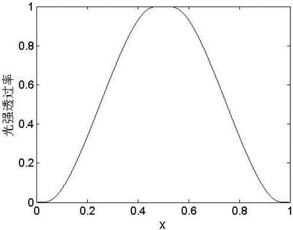
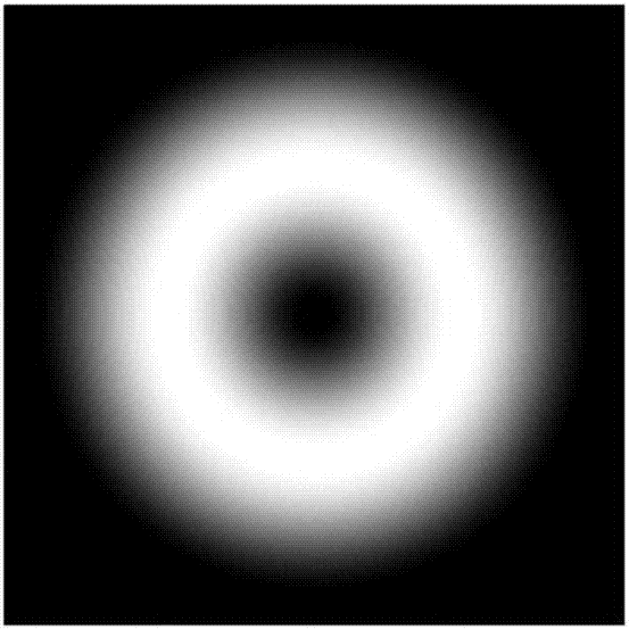
[0062] Amplitude modulation functions such as figure 1 As shown, will figure 1 Rotate along the x=0 axis to obtain the transmittance distribution of the amplitude modulation filter (i.e. the modulator of the present invention), the light intensity transmittance of the amplitude modulation filter is as follows figure 2 shown.
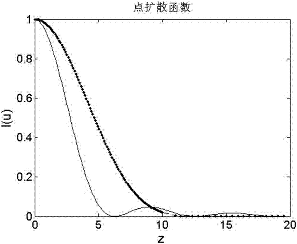
[0063] The comparison between the point spread function and the point spread function without amplitude modulation is as follows image 3 , where the dotted line is the case of amplitude modulation, and the solid line is the case of no amplitude modulation.
[0064] The attenuation speed of the focused spot after a...
Embodiment 2
[0067] This embodiment is applied to an amplitude modulation confocal microscope, and the amplitude modulation confocal microscope includes a common confocal microscope system and a modulation plate of the present invention. The amplitude modulation confocal microscope consists of an amplitude modulation plate and a common confocal microscope system. The amplitude modulation plate is placed in front of the focusing objective lens of the confocal microscope to modulate the amplitude of the excitation light incident on the sample.
[0068] Specific as Image 6 As shown, a common confocal microscope system includes a laser 1, a first aperture stop 2, a first objective lens 3, a beam splitter 4, a second objective lens 6, a sample 7, a focal plane 8, a scanning stage 9, and a third objective lens 10 , the second aperture stop 11 and the detector 12, the laser light emitted by the laser device 1 passes through the first aperture stop 2 and the first objective lens 3 successively an...
Embodiment 3
[0073] This embodiment is applied in an optical path composed of a laser, an objective lens and a detector, such as Figure 10 shown.
[0074] This embodiment adopts a random parameter, τ L =0.2,τ R =0.15, at this time, the amplitude modulation function is:
[0075]
[0076]
[0077] The corresponding amplitude modulation function is as Figure 11 As shown, will Figure 11 Rotate along the x=0 axis to obtain the transmittance distribution of the amplitude modulation filter (i.e. the modulator of the present invention), the light intensity transmittance of the amplitude modulation filter is as follows Figure 12 shown.
[0078] The point spread function of this parameter is as follows Figure 13 As shown, the resulting facula as Figure 14 As shown, it can be seen that the side spots of the light spot at this time are smaller than the case without amplitude modulation, and larger than the case of the typical parameters in Example 1, but the central spot is smaller ...
PUM
 Abstract
Description
Claims
Application Information
 - R&D
- Intellectual Property
- Life Sciences
- Materials
- Tech Scout
- Unparalleled Data Quality
- Higher Quality Content
- 60% Fewer Hallucinations
Browse by: Latest US Patents, China's latest patents, Technical Efficacy Thesaurus, Application Domain, Technology Topic, Popular Technical Reports.
© 2025 PatSnap. All rights reserved.Legal|Privacy policy|Modern Slavery Act Transparency Statement|Sitemap|About US| Contact US: help@patsnap.com


