Nanoparticles and their use for multifunctional bioimaging

a bioimaging and nanoparticle technology, applied in the direction of x-ray constrast preparations, nmr/mri constrast preparations, powder delivery, etc., can solve the problem that optical imaging alone is very limited by the spatial resolution that can be achieved, and the technique does not allow direct and gross visualization of tumor tissue with the naked eye, so as to reduce the leakage of toxic cadmium ions, improve brightness, and improve the effect of brightness

Inactive Publication Date: 2012-03-06
UNIV OF FLORIDA RES FOUNDATION INC
View PDF23 Cites 26 Cited by
  • Summary
  • Abstract
  • Description
  • Claims
  • Application Information

AI Technical Summary

Benefits of technology

[0039]In a preferred embodiment, the multifunctional contrast agent is a yellow-emitting monodisperse, ultra-small (e.g., less than 10 nm), water-soluble CdS:Mn / ZnS nanoparticle (zinc sulfide capped and manganese doped cadmium sulfide quantum dot). Furthermore, the contrast agent is preferably coated with a systemically non-toxic material, such as amorphous silica. The nanoparticles of the present invention (also referred to herein interchangeably as NP, particles, quantum dots, Qdots, QD, probes, nanocrystals, core / shell nanocrystals, detection agents, and / or contrast agents) are superior to conventional fluorescent dyes because of their remarkable photostability, brightness, and suitability for in vivo multifaceted bioimaging.
[0040]In some embodiments, the quantum dots further comprise a coating (outer shell), which can passivate the Cds:Mn / ZnS portions of the nanoparticle, improve brightness and, if necessary, reduce leakage of toxic cadmium ions. Preferably, the coating comprises silica. The coating can be amine-functionalized to the ZnS shell, for example (an amine-functionalized silica coating). The size of the quantum dot will vary with the thickness of the coating.
[0046]The multifunctional contrast agents of the present invention allow enhanced anatomical information to be obtained. As used herein, the term “enhanced” means that the image or information obtained by using the multifunctional contrast agent is of improved quality over the image or information that would be obtained by using no contrast agent. The enhanced anatomical information may be obtained via computed tomography, positron emission tomography, or magnetic resonance imaging, for example. The enhanced functional information may be obtained via near-infrared fluorescence imaging, for example.

Problems solved by technology

However, since low localization information is characteristic of optical imaging, one or more additional modalities may be required for diagnosing pathologies deeper within the body.
For example, MRI in the presence of contrast agents has very high sensitivity for detecting breast tumors, but very low specificity for the detection of cancerous tissue.
However, when applications such as breast imaging are envisioned, optical imaging by itself is very limited by the spatial resolution that can be achieved.
Three-dimensional CT and MR imaging are routinely used for diagnosis of brain tumors, although these techniques do not allow the direct and gross visualization of tumor tissue with a bare eye.
Further, these imaging techniques do not provide surgical guidance to surgeons for the tumor resection in real-time.
Most of the unsuccessful brain tumor surgeries, which sometimes result in major neurological disabilities, were primarily responsible for the lack of technological advancement in demarcating tumor boundaries.
The use of organic dyes may not be suitable for real-time imaging as these dyes often undergo rapid photobleaching process.
However, due to the dissimilar chemical properties (e.g., ionic radius, valence state) between the RE ion and host cation (Cd2+, Zn2+), efficient doping of RE ions into II-VI semiconductor host is not favorable (Bol et al., Chem. Mater., 2002, 14:1121).
Control of the surface has been a critical issue to obtain highly luminescent, photostable nanocrystals.
However, luminescent Qdots synthesized by hot solution phase chemistry have a poor solubility in water, resulting in a poor compatibility with biological environments and aqueous assay conditions (Chan et al., Science, 1998, 281:2016; Bruchez et al., Science, 1998, 281:2013; Wu et al., Nat. Biotechnol., 2003, 21:41; Larson et al., Science, 2003, 300:1434; Dubertret et al., Science, 2002, 298:1759; Gerion et al., J. Phys. Chem. B, 2001, 105:8861).
These NIR probes, however, will not be suitable for the detection of brain tumors.
It is unlikely that an optical signal will pass through the skull, severely limiting any brain related application of these optical probes.

Method used


Image

  • Nanoparticles and their use for multifunctional bioimaging
  • Nanoparticles and their use for multifunctional bioimaging
  • Nanoparticles and their use for multifunctional bioimaging

Examples


example 1

Core / Shell Structure and Size of Nanocrystals

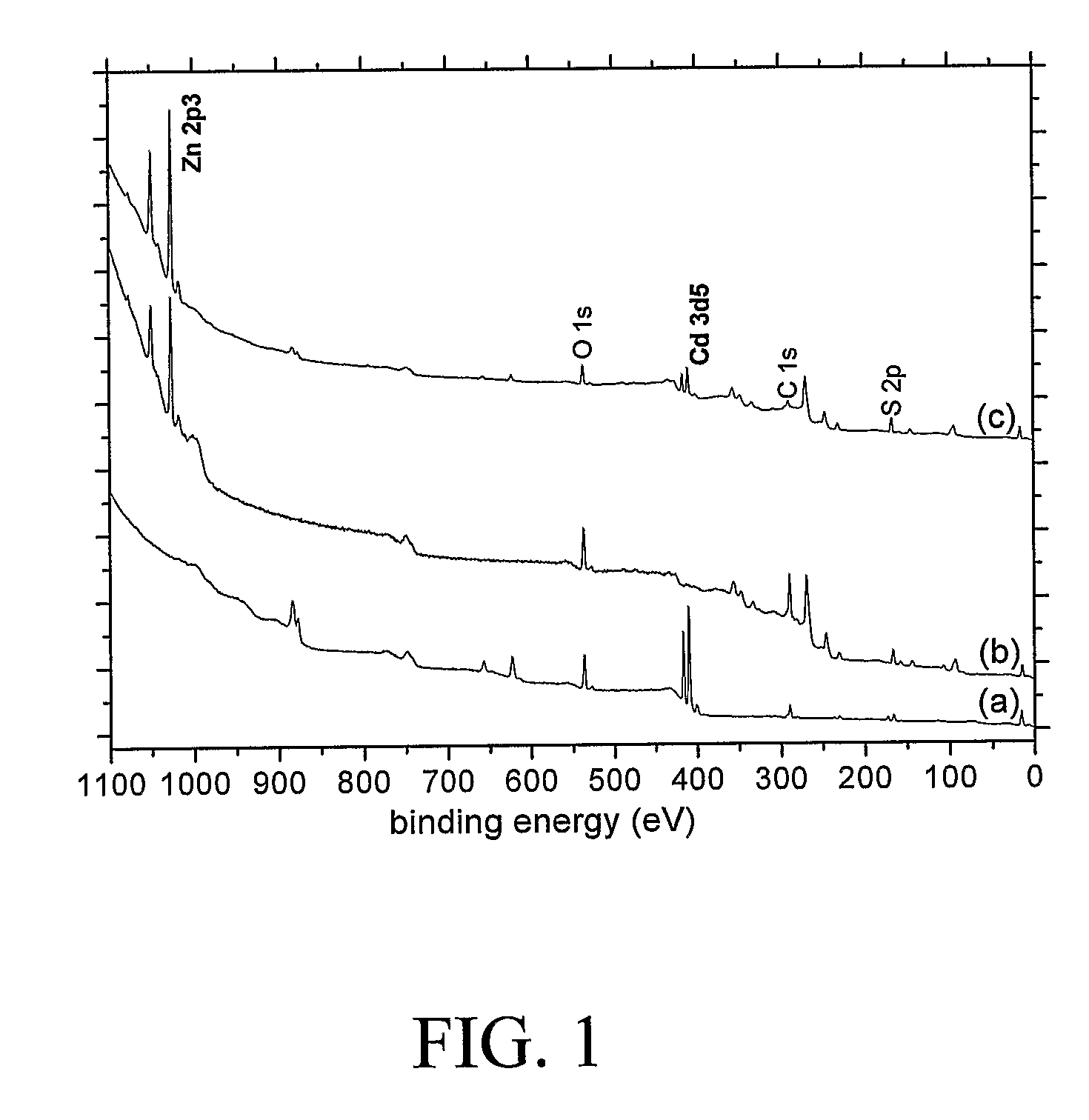
[0167]It has been reported that synthesized nanocrystals consist of a CdS core / ZnS shell structure, based on UV-visible absorption spectroscopy and x-ray photoelectron spectroscopy (XPS) / energy-dispersive spectroscopy (EDS) (Yang, H. and P. H. Holloway, Appl. Phys. Lett. 2003, 82:1965-1967). Since XPS is a surface sensitive method and EDS is a ‘bulk’ method of analysis (Brundle, C. R., Encyclopedia of Materials Characterization, (Eds: C. R. Brundle, C. A. Evans, Jr., S. Wilson), Butterworth-Heinemann, Boston 1992), the samples with CdS core / ZnS shell structure should experience an attenuation of the signals from buried core element, i.e., Cd, in XPS relative to EDS. Thus XPS spectra should be dominated by the shell, while EDS spectra should exhibit the elements in both the shell and the core structure averaged over many nanocrystal thickness. XPS survey spectra of CdS:Mn, ZnS:Mn, and CdS:Mn / ZnS core / shell nanocrystals are shown in FIG. 1....

example 2

Photoluminescence (PL) and Quantum Yield

[0168]PL emission spectra, obtained using 325 nm HeCd laser excitation, of n-dodecanethiol-passivated and ZnS-passivated CdS:Mn nanocrystals are compared in FIG. 3A and FIG. 3B, respectively. Note that PL measurements were carried out in the solid-state sample, i.e., ˜200 nm thick CdS:Mn / ZnS nanocrystal layers on the glass substrate. The Mn2+ 4T1-6A1 transition at ˜600 nm is observed from both nanocrystalline samples. In addition to the Mn emission at ˜600 nm, emission from a surface-related defect (shallow trap) is observed at ˜450 nm from organically passivated nanocrystals. This defect emission originates from the localized surface states in the band gap, which presumably are formed by the lack of bonding to surface S ions. In contrast, no defect-related emission is observed from inorganically passivated nanocrystals, indicating the successful complete passivation of CdS:Mn core surface by the ZnS shell layer.

[0169]The quantum yields of CdS...

example 3

Effects of UV irradiation and Photooxidation

[0170]The change of PL emission intensity from organically and inorganically passivated CdS:Mn during 400 nm UV irradiation was monitored at room temperature using a monochromatized 300 W Xe light source (FIG. 5). The 400 nm UV irradiation was estimated to have a powder density of 655 μW / cm2. Organically passivated CdS:Mn nanocrystals exhibit a significant reduction (˜45% after 3 hours) of the PL emission intensity upon UV exposure, while CdS:Mn / ZnS core / shell nanocrystals show an increased PL intensity (˜40% after 3 hours). The reduced PL emission intensity of n-dodecanethiol-passivated CdS:Mn nanocrystals presumably results from the fact that the bonding between the Cd (from nanocrystal) and S ions (from organic passivating species) at the surface is deteriorated by UV exposure. Accordingly, the density of nonradiative relaxation paths increases at the surface, resulting in a decreased PL emission intensity (C. Jin, C., J. Yu, L. Sun, K....


PUM

PropertyMeasurementUnit
wavelengthaaaaaaaaaa
sizesaaaaaaaaaa
sizesaaaaaaaaaa

Abstract

The present invention relates to fluorescent, radio-opaque and magnetic quantum nanoparticles, useful as multifunctional contrast agents or probes for in vivo bioimaging, and methods of their use. The invention provides for multifaceted bioimaging (e.g., intra-arterial pre-operative brain mapping and broad based in vivo diagnostic imaging), including imaging of various cell types, such as stem cells.

Description

CROSS-REFERENCE TO RELATED APPLICATIONS[0001]This application is the National Stage of International Application Number PCT / US2005 / 015266, filed May 2, 2005, which claims benefit of U.S. Provisional Application Ser. No. 60 / 567,330, filed Apr. 30, 2004, each of which is hereby incorporated by reference herein in its entirety, including any figures, tables, nucleic acid sequences, amino acid sequences, and drawings.GOVERNMENT SUPPORT[0002]This invention was made with government support under Grant No. DAAD19-01-1-0603 awarded by the Army Research Office. The government has certain rights in the invention.BACKGROUND OF THE INVENTION[0003]The human body is composed of tissues that are generally opaque. In the past, exploratory surgery was one common way to look inside the body. Today, physicians can use a vast array of imaging methods to obtain information about a patient. Some non-invasive imaging techniques include modalities such as X-ray, magnetic resonance imaging (MRI), computer-a...

Claims


Application Information

Patent Timeline
Patent Type & Authority Patents(United States)
IPC IPC(8): A61B5/00A61B5/055A61K49/00A61K49/04A61K49/08A61K49/14A61K49/18
CPCA61K49/0002A61K49/0067A61K49/0423A61K49/085A61K49/14A61K49/183B82Y5/00Y10S977/774A61P43/00
Inventor SANTRA, SWADESHMUKULHOLLOWAY, PAUL H.MERICLE, ROBERT A.YANG, HEESUNWALTER, GLENN A.
Owner UNIV OF FLORIDA RES FOUNDATION INC
Why Eureka
Try Eureka