
System and method for reducing background noise in magnetoencephalogram detection

A technology of background noise and magnetoencephalography, applied in diagnostic recording/measurement, medical science, sensors, etc., can solve the problems of limiting the flexibility of magnetoencephalography, high requirements for external conditions, and limited scope of application, etc. Limited range, poor real-time performance, and low-cost effects

Inactive Publication Date: 2017-06-20
UNIV OF SHANGHAI FOR SCI & TECH
View PDF4 Cites 12 Cited by
  • Summary
  • Abstract
  • Description
  • Claims
  • Application Information

AI Technical Summary

Problems solved by technology

The more common method in the prior art is to construct a magnetic shielding room, and place the magnetoencephalograph in the magnetic shielding room. Plotter usage flexibility
There is another method in the prior art, see the US patent, the patent name is Noise cancellation inmagnetoencephalography and electroencephalography with isolated reference sensors, the authorized patent number is US7729740B2, and the patent authorization time is January 01, 2010. The present invention adopts the method of adding sensors , the main sensor and reference sensor are set on both sides of the established electromagnetic field shielding layer, the main sensor is on the side close to the detected side, the reference sensor is set on the side of the ambient noise, the correction signal is obtained through the reference sensor, the main sensor signal minus the correction The signal is noise-free signal (noise-free signal). This prior technology has considerable advantages, but there are some essential deficiencies, such as complex system structure, cumbersome implementation process, inconvenient implementation, increased cost, affecting detection performance, and limited scope of application.

Method used


Image

  • System and method for reducing background noise in magnetoencephalogram detection

Examples


Embodiment Construction

[0014] The present invention will be further described below in conjunction with drawings and embodiments.

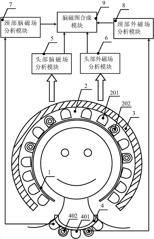
[0015] Such as figure 1 As shown, a background noise weakening system in magnetoencephalogram detection includes a head-mounted flexible substrate 1, a magnetic sensor array layer 2, a magnetic shielding layer 3, a wearable magnetic field sensor neck ring 4, a head brain magnetic field analysis module 5, Head external magnetic field analysis module 6 , neck brain magnetic field analysis module 7 , neck external magnetic field analysis module 8 , magnetoencephalogram synthesis module 9 .

[0016] A magnetic sensor array layer 2 is arranged on the outside of the head-mounted flexible substrate 1. The magnetic sensor array layer 2 is composed of a brain magnetic field sensor array 201 and an external magnetic field sensor array 202. The brain magnetic field sensor array 201 and the external magnetic field sensor array 202 are distributed on the left and right sides of the ...


PUM


Abstract

The invention relates to a system and a method for reducing background noise in magnetoencephalogram detection. A magnetic sensor array layer is arranged at the outer side of a head-mounted flexible substrate; a brain magnetic field sensor array and an outer magnetic field sensor array are distributed on left and right hemispheres of the brain; a magnetic shielding layer is arranged outside the magnetic sensor array layer; and a neck ring of a wearable magnetic field sensor is arranged on the neck of a human body. reduction of the background noise in magnetoencephalogram detection is achieved by collecting and analyzing a brain magnetic field of the head and an outer magnetic field of the head, analyzing the brain magnetic field of the neck and the outer magnetic field of the neck, fusing brain magnetic field information, carrying out noise analysis on the outer magnetic field information, obtaining a reference noise background signal, fusing the brain magnetic field information and subtracting the reference noise background signal, and a magnetoencephalogram with a high signal-noise ratio is obtained. The system and the method have the characteristics of being simple, convenient to implement, high in sensitivity, low in implementation cost, high in reliability, small in space and high in flexibility.

Description

technical field [0001] The present invention relates to a system and method for reducing background noise, in particular to a system and method for reducing background noise in magnetoencephalogram detection, which are mainly used in brain science, life medicine, biotechnology, health detection, disease diagnosis and treatment, human-computer interaction, and intelligent control. A system and method for weakening background noise in magnetoencephalogram detection in the fields of behavior organization and the like. Background technique [0002] Magnetoencephalography (MEG for short) detection is a completely non-invasive and non-radioactive brain function image detection technology for the human body. , behavioral organization and other fields play a very important role. Magnetoencephalography does not need to touch the skin, and there will be no artifacts caused by it. It can directly reflect the activity state of the magnetic field source in the brain, and can determine t...

Claims


Application Information

Patent Timeline
IPC IPC(8): A61B5/04A61B5/00
CPCA61B5/6822A61B5/7203A61B2576/026A61B5/242
Inventor 高秀敏曾祥堉詹秋芳张荣福
Owner UNIV OF SHANGHAI FOR SCI & TECH
Learn More