Cell plating device taking magnetic liquid as medium

A magnetic liquid and medium technology, applied in the field of biomedical engineering, can solve problems such as failure, and achieve the effect of maintaining cell activity and uniform plating

Pending Publication Date: 2017-06-20
KUNMING UNIV OF SCI & TECH
View PDF0 Cites 0 Cited by
  • Summary
  • Abstract
  • Description
  • Claims
  • Application Information

AI Technical Summary

Problems solved by technology

These operations have high requirements for experimenters, are more subjective, and require rich experience and familiar skills. A slight negligence or careless operation will cause the experiment to fail.

Method used


Image

  • Cell plating device taking magnetic liquid as medium
  • Cell plating device taking magnetic liquid as medium
  • Cell plating device taking magnetic liquid as medium

Examples


Embodiment 1

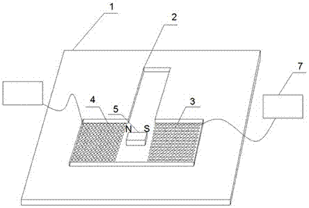
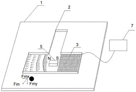
[0031] A cell plating device using magnetic liquid as the medium, including a silicon chip substrate 1 (rectangular 100×100mm), T-shaped channel 2, microcoil I3, microcoil II4, permanent magnet I5, permanent magnet II6, programmable AC power supply 7. Microcoil I3 and microcoil II4 are provided on the silicon wafer substrate 1 (in this embodiment, microcoil I3 and microcoil II4 are fabricated on the silicon wafer substrate 1 by photolithography and electroplating), microcoil I3 and microcoil II4 On a straight line with a gap between the two; the T-shaped channel 2 is sealed and fixed on the silicon substrate 1, the microcoil I3 and the microcoil II4 are located below the horizontal channel of the T-shaped channel 2, the microcoil I3 and the microcoil The gap between II4 is directly opposite to the vertical channel of T-shaped channel 2; there is a transparent cover plate above T-shaped channel 2, and the cover plate is provided with permanent magnet I5 or permanent magnet II6, ...

Embodiment 2

[0035] Referring to the structure of embodiment 1, the difference between this embodiment and embodiment 1 is that the number of permanent magnets I5 and permanent magnets II6 are two or more respectively. This magnet structure can generate a higher gradient magnetic field and increase the magnetic fluid The magnetic buoyancy force on the cell.

Embodiment 3

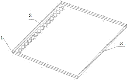
[0037]With reference to the structure of Embodiment 1, the difference between this embodiment and Embodiment 1 is that the microcoil I3 of the present invention is in the form of a rectangular cell, including a plurality of parallel top wires 10 and a plurality of bottom wires 9 parallel to each other, and the top An isolation layer is provided between the wire 10 and the bottom wire 9, the bottom wire 9 is located on the silicon substrate 1, the top wire 10 is located on the isolation layer, the top wire 10 and the bottom wire 9 are perpendicular to each other, and have a 90° phase difference of sine and cosine The current is applied to the two crossed wires at the same frequency f to generate a magnetic field gradient. The microcoil II4 has the same structure as the microcoil I3; the line spacing between the microcoil I3 and the microcoil II4 is 10 mu m and 20 mu m, wire diameter is 4 mu m, sine and cosine currents with a 90° phase difference are applied to the crossed two ...


PUM

PropertyMeasurementUnit
Diameteraaaaaaaaaa

Abstract

The invention relates to a cell plating device taking magnetic liquid as a medium, belonging to the field of biomedical engineering. The cell plating device comprises a silicon wafer substrate, a T-shaped channel, a micro-coil I, a micro-coil II, a permanent magnet I, a permanent magnet II and a programmable alternating current (AC) power source, wherein the silicon wafer substrate is provided with the micro-coil I and the micro-coil II; the micro-coil I and the micro-coil II are positioned on the same straight line, and a gap is reserved between the micro-coil I and the micro-coil II; the T-shaped channel is fixed on the silicon wafer substrate in a sealing way; the micro-coil I and the micro-coil II are positioned under a horizontal channel of the T-shaped channel; the gap between the micro-coil I and the micro-coil II just faces to a vertical channel of the T-shaped channel; a transparent cover plate is arranged above the T-shaped channel, and is provided with the permanent magnet I or the permanent magnet II; the permanent magnet I or the permanent magnet II is positioned just above the gap between the micro-coil I and the micro-coil II; all leads of the micro-coil I and the micro-coil II are connected with the programmable AC power source. The cell plating device can effectively reduce the disturbance problem caused in a manual operation process, and increases cell plating efficiency.

Description

technical field [0001] The invention relates to the field of biomedical engineering, in particular to a cell plating device with magnetic liquid as the medium. Background technique [0002] The in vitro culture of cells and tissues is an important means of life science research. Some cells and tissues can grow in suspension, but a significant fraction of mammalian cells require surface attachment. Therefore, in addition to having good transparency, non-toxicity and asepticity, the culture flasks, culture plates and culture dishes used to provide the in vitro culture environment of cells also need to enable cells to adhere to the wall, divide and grow. However, in practical applications, due to the small volume and mass of cells, a slight disturbance from the outside world will have a significant impact on the movement of cells. Uneven cell plating will lead to poor cell growth and other problems, leading to the failure of the experiment. [0003] At present, in order to a...

Claims


Application Information

Patent Timeline
IPC IPC(8): C12M3/00C12M1/42
CPCC12M25/06C12M45/07
Inventor 黄爽何永清焦凤
Owner KUNMING UNIV OF SCI & TECH
Why Eureka
Try Eureka