
Intelligent switch equipment detection and debugging device and system, and intelligent switch equipment detection joint debugging method

An intelligent switch and equipment detection technology, which is applied in the direction of measuring devices, circuit breaker testing, and electrical measurement, can solve problems such as low level of intelligence and single function of debugging equipment, achieve flexible configuration, improve detection and debugging efficiency and intelligence Horizontal, versatile effects

Inactive Publication Date: 2017-06-20
PINGGAO GRP +2
View PDF5 Cites 8 Cited by
  • Summary
  • Abstract
  • Description
  • Claims
  • Application Information

AI Technical Summary

Problems solved by technology

[0004] The invention provides an intelligent switchgear detection and debugging device, system and joint debugging method to solve the problem that the existing intelligent switchgear debugging is too dependent on the manufacturer's specific debugging background, and the debugging equipment has a single function and a low level of intelligence

Method used


Image

  • Intelligent switch equipment detection and debugging device and system, and intelligent switch equipment detection joint debugging method
  • Intelligent switch equipment detection and debugging device and system, and intelligent switch equipment detection joint debugging method
  • Intelligent switch equipment detection and debugging device and system, and intelligent switch equipment detection joint debugging method

Examples


Embodiment Construction

[0024] The technical solutions of the present invention will be further described in detail below in conjunction with the accompanying drawings.

[0025] Embodiment of the intelligent switchgear detection and debugging device of the present invention

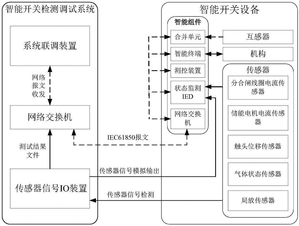
[0026] The intelligent switching device detection and debugging device of this embodiment includes a sensor signal IO device, a system joint debugging device and a network switch. It is used to realize sensor function test, and intelligent component and sensor interaction function test.

[0027] figure 1 A specific detection and debugging device for intelligent switchgear is given, which is composed of a sensor signal IO device, a system joint debugging device and a network switch. The dotted lines in the figure represent optical fibers, and the solid lines represent cables or network cables. The system joint debugging device is connected to the system internal switch through Gigabit optical fiber, the sensor signal IO device...


PUM


Abstract

The invention relates to an intelligent switch equipment detection and debugging device and system, and an intelligent switch equipment detection joint debugging method. The device comprises a system joint debugging device, a network switch and a sensor signal IO device that are connected in sequence. The system joint debugging device is used for conducting system joint debugging of intelligent switch equipment and carrying out inter-operating function tests on intelligent assemblies. The sensor signal IO device is used for carrying out sensor function tests as well as intelligent assembly and sensor interaction function tests. The system comprises the above intelligent switch equipment detection and debugging device and intelligent switch equipment connected and communicated with the intelligent switch equipment detection and debugging device. The method includes the following steps: automatically generating a network message after the intelligent switch equipment detection and debugging device receives control instruction parameters set by a user, sending the network message to an intelligent terminal, and finishing a control function test through comparison of consistency between switch actual motions and issued control instructions. The intelligent switch equipment detection and debugging device is improved in detection debugging efficiency, has a flexible configuration function of test functions, is easy and convenient to operate, and is high in automation.

Description

technical field [0001] The invention belongs to the field of detection and debugging of intelligent substations, and in particular relates to a detection and debugging device, system and joint debugging method of an intelligent switchgear. Background technique [0002] Smart grid construction is an important part of the national "Twelfth Five-Year" plan. Smart substations are one of the important links in smart grid construction, and smart switches are key equipment in smart substation systems. They are crucial to the safe operation of power transmission and transformation lines. important. The detection and debugging of smart switch equipment is one of the important contents of smart substation system debugging. It is an important link to test the quality of smart switches and ensure the safe operation of the power grid. It generally includes two parts: the functional test of sensors and individual components of smart components, and the overall joint debugging of smart swi...

Claims


Application Information

Patent Timeline
Patent Type & Authority Applications(China)
IPC IPC(8): G01R31/327
CPCG01R31/3271
Inventor 孙银山寇新民钟建英尹军华谭盛武袁端磊李少华高群伟王春艳李琼可
Owner PINGGAO GRP
Learn More