High speed aberration correction method based on machine learning

A technology of aberration correction and machine learning, which is applied in the field of high-speed aberration correction, can solve problems such as slow correction speed, and achieve the effects of slow solution speed, improved microscopic imaging resolution, high-speed and accurate correction

Active Publication Date: 2017-06-20
ZHEJIANG UNIV
View PDF6 Cites 21 Cited by
  • Summary
  • Abstract
  • Description
  • Claims
  • Application Information

AI Technical Summary

Problems solved by technology

The weakness of the traditional adaptive correction algorithm is that the correction speed is very slow. Researchers have also proposed a series of algorithms to speed up the correction speed, such as the COAT algorithm

Method used


Image

  • High speed aberration correction method based on machine learning
  • High speed aberration correction method based on machine learning
  • High speed aberration correction method based on machine learning

Examples


Embodiment Construction

[0032] The present invention will be further described below in conjunction with drawings and embodiments.

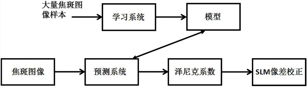
[0033] Since the use of wavefront detectors will increase the complexity of the optical path and bring a series of problems such as wavefront measurement errors, the present invention does not use wavefront detectors, but directly analyzes the wavefront phase distribution according to the distribution of focused spots .

[0034] Embodiments of the present invention are as follows:

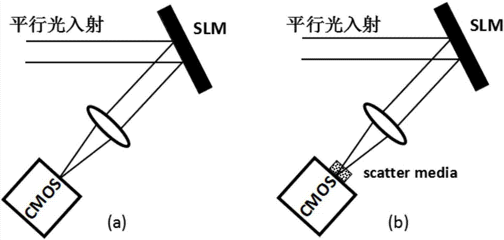
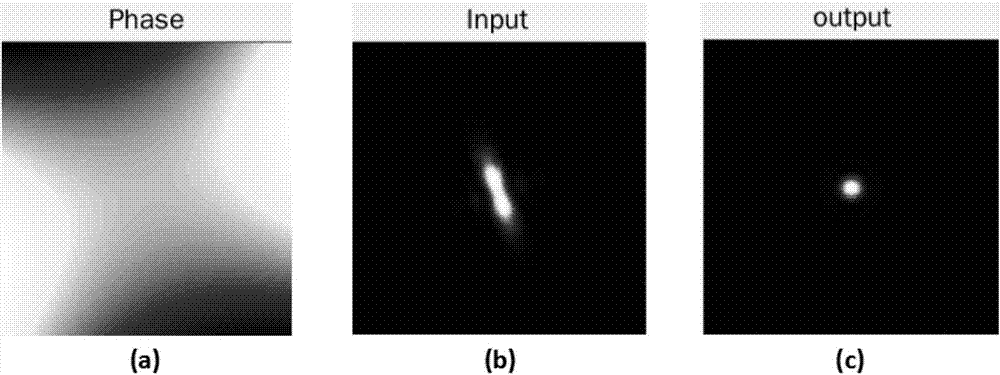
[0035] 1) The parallel light beam is first reflected by the spatial light modulator that does not load the wavefront phase distribution, and then focused by the lens to obtain an ideal focused spot at the focal plane position;

[0036] 2) Use the Zernike polynomial to calculate the wavefront phase distribution of the incident beam using the following formula:

[0037]

[0038] Among them, a k Indicates the kth Zernike coefficient, k=1,2,3,4,5,6,...n, Z k Represents the expression of t...


PUM


Abstract

The invention discloses a high speed aberration correction method based on machine learning. The incident parallel beam passes through the spatial light modulator that does not load the wavefront phase distribution to obtain the ideal focused spot. A series of wavefront phase distributions are obtained using the Zenike polynomial processing, and each wavefront phase distribution is loaded into the spatial light modulator to obtain a distorted focused spot. The light intensity distribution of each distorted focused spot and the respective Zenike coefficients under the incident wave wavefront distribution are input to the machine learning training to obtain the correction model. The intensity distribution of the distorted focused spot pattern of the scattering medium to be measured is input to the calibration model to obtain the values of the respective Zenike coefficients, and by taking the negative value calculation, the corrected phase distribution is obtained and loaded into the spatial light modulator to achieve aberration correction. The method can realize the high speed optical aberration correction of the optical path, the correction speed is fast and the accuracy is high, and the problem that the traditional adaptive optical algorithm is slow is solved.

Description

technical field [0001] The invention belongs to the field of optical microscopic imaging, in particular to a high-speed aberration correction method based on machine learning. Background technique [0002] When microscopic imaging is used for deep imaging of biological tissue, the wavefront aberration caused by the production accuracy error of optical components and the inhomogeneity of the refractive index of biological tissue in the optical path will seriously affect the focusing of the spot, and with the imaging depth The increase of the signal-to-noise ratio and resolution decreases, and the imaging quality drops sharply. In response to this phenomenon, researchers have proposed many solutions, among which adaptive optics technology is a common and effective solution. [0003] The principle of adaptive optics technology to improve imaging quality is as follows: First, the wavefront sensor is used to measure the wavefront distortion of the optical system caused by variou...

Claims


Application Information

Patent Timeline
Patent Type & Authority Applications(China)
IPC IPC(8): G02B27/00G06N99/00
CPCG02B27/0012G06N20/00
Inventor 龚薇斯科章一叶
Owner ZHEJIANG UNIV
Why Eureka
Try Eureka