Over-current protection element with protective shell
A technology for protecting shells and components, applied to resistors with positive temperature coefficients, resistors with current response, etc., can solve the problems of not being able to enter the high-resistance state and not being able to achieve over-current protection, etc.
- Summary
- Abstract
- Description
- Claims
- Application Information
AI Technical Summary
Problems solved by technology
Method used
Image
Examples
Embodiment 1
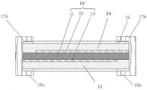
[0043] A SMD type PTC thermistor such as figure 1 As shown, the polymer core material composed of the polymer substrate and the conductive filler is closely attached to the metal electrode sheets on both sides to form a sheet of composite material. This sheet is prepared into an SMD type PTC thermistor through a series of PCB processes. The chip 10 with the positive temperature effect of resistance includes a polymer core material 11 and upper and lower metal electrode sheets 12, 13, and the upper and lower metal electrode sheets 12 , The upper and lower surfaces of 13 have upper and lower insulating layers 14, 15, metal foil 16, and upper electrodes one and two 17a, 17b; lower electrodes one and two 18a, 18b.
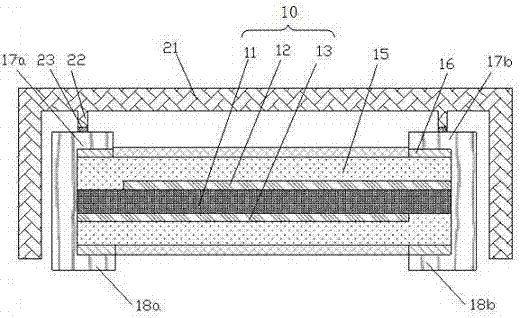
[0044] Such as figure 2 As shown, a protective shell 21 covers the outside of the SMD type PTC thermistor, and the inner space of the protective shell 21 is larger than the SMD type PTC thermistor, so that the protective shell 21 and the SMD type PTC thermistor Chip...
Embodiment 2
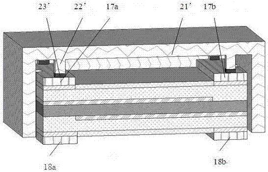
[0047] The PTC thermistor of the present embodiment is identical with embodiment 1, is the SMD type PTC thermistor, but in the SMD type PTC thermistor, a protective shell 21 ' with openings on both sides is added, and its three-dimensional structure schematic diagram is as follows image 3shown. The two openings of the protective shell 21' are on two adjacent surfaces, namely the front and the bottom, and the lower end electrodes 1, 2 18a, 18b of the PTC thermistor should be located on the surface where one of the openings is located, and slightly higher than this opening on the surface. The inner wall of the protective shell 21' is provided with a support rod or a boss 22', and is fixedly connected with the first and second electrodes 17a, 17b of the PTC thermistor upper end electrodes with an adhesive medium 23'. The protective shell 21' can protect the PTC thermistor from the upper pressure. At the same time, the protective shell 21' can be bonded to the PCB protection bo...
Embodiment 3
[0049] The PTC thermistor of this embodiment is the same as that of Embodiment 1, and is an SMD type PTC thermistor, but a protective shell 21'' with openings on three sides is added to the SMD type PTC thermistor, and the lower terminal electrode of the PTC thermistor is , 18a, 18b are located on the surface where one of the openings is located, and are slightly higher than the surface where the opening is located. There is no opening on the other side parallel to this side, which can protect the PTC thermistor from the upper pressure. The other two openings of the protective shell 21'' can be in adjacent positions, such as Figure 4 As shown, the protective shell 21'' is open on the front, side and lower sides; it can also be in a parallel position; as Figure 5 The front and rear sides and the lower side of the protective shell 21'' shown are open.
PUM
| Property | Measurement | Unit |
|---|---|---|
| Thickness | aaaaa | aaaaa |
Abstract
Description
Claims
Application Information
 - R&D
- Intellectual Property
- Life Sciences
- Materials
- Tech Scout
- Unparalleled Data Quality
- Higher Quality Content
- 60% Fewer Hallucinations
Browse by: Latest US Patents, China's latest patents, Technical Efficacy Thesaurus, Application Domain, Technology Topic, Popular Technical Reports.
© 2025 PatSnap. All rights reserved.Legal|Privacy policy|Modern Slavery Act Transparency Statement|Sitemap|About US| Contact US: help@patsnap.com


