Electrodynamic induction loudspeaker

A loudspeaker, electrodynamic technology, applied in the field of loudspeakers, can solve the problems of low sensitivity and large misalignment of ordinary inductive loudspeakers, and achieve the effect of ensuring isotropy, reducing distortion, and reducing distortion

Active Publication Date: 2017-06-20
NANJING QIAOSHENG FLUCTUATION TECH
View PDF11 Cites 3 Cited by
  • Summary
  • Abstract
  • Description
  • Claims
  • Application Information

AI Technical Summary

Problems solved by technology

[0005] The purpose of the present invention is to overcome the problems of the prior art, provide an induction dynamic speaker, and solve the problems of large misalignment of common dynamic speakers and low sensitivity of common induction speakers

Method used


Image

  • Electrodynamic induction loudspeaker
  • Electrodynamic induction loudspeaker
  • Electrodynamic induction loudspeaker

Examples


Embodiment 1

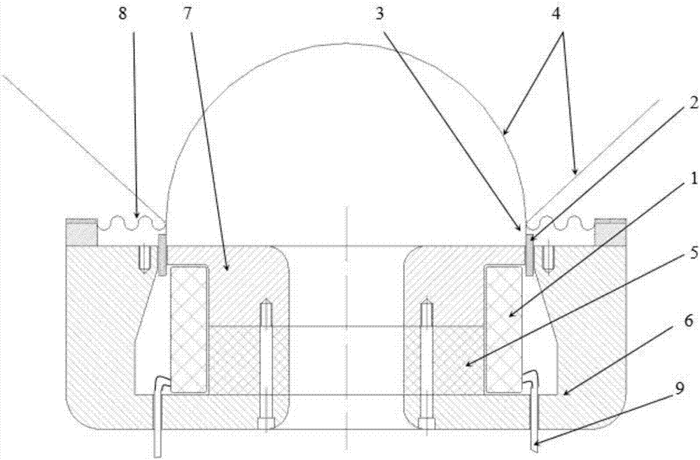
[0037] An internal magnetic induction electrodynamic loudspeaker, such as figure 1 As shown, it includes excitation coil 1, induction voice coil 2, voice coil bobbin 3, sound membrane 4, magnet steel 5, lower magnetic plate 6, upper magnetic splint 7, centering strut 8 and signal feeder 9. The magnetic steel 5 is installed between the central columns of the lower magnetically conductive plate 6 and the upper magnetically conductive splint 7 and is fixed or glued together by bolts. The excitation coil 1 is fastened on the central magnetic pole composed of the lower end of the upper magnetic splint 7 and the magnetic steel 5. The excitation coil 1 is connected to the signal feeder 9 and the signal feeder passes through the passage of the lower magnetic conductive plate. hole and connect the external audio current signal. The magnetic steel 5 is a permanent magnet with high resistivity, and the upper magnetically conductive splint 7 and the lower magnetically conductive plate 6 ...

Embodiment 2

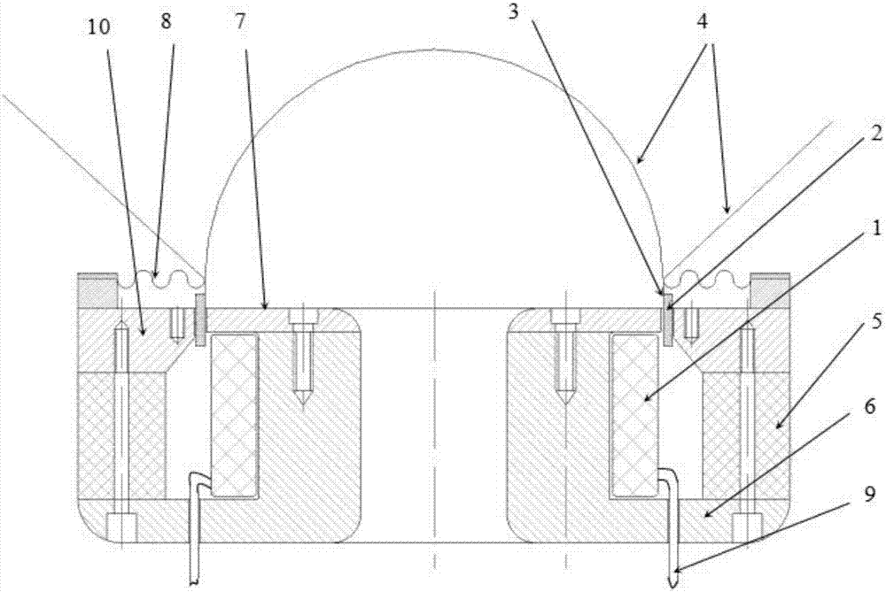
[0039] An external magnetic induction electrodynamic loudspeaker, such as figure 2 As shown, it includes excitation coil 1, induction voice coil 2, voice coil bobbin 3, sound film 4, magnetic steel 5, lower magnetic plate 6, upper magnetic splint 7, centering strut 8, signal feeder 9 and outer guide magnetic board10. The magnetic steel 5 is a high-resistivity permanent magnet, and the upper magnetically conductive splint 7, the lower magnetically conductive plate 6 and the outer magnetically conductive plate 10 are all soft magnetic materials with high magnetic permeability and high resistivity, which can reduce the eddy current loss of the magnetic circuit Small to increase the electro-acoustic conversion efficiency. The upper magnetically conductive splint 7 is installed on the upturned end surface of the lower magnetically conductive plate 6 and fixed together by bolts or glue, and the magnetic steel 5 is installed between the outer upper end surface of the lower magnetic...


PUM


Abstract

The invention relates to an electrodynamic induction loudspeaker. Technical characteristics of the electrodynamic induction loudspeaker are as follows: an induction voice coil is mounted in a magnetic gap formed between magnetic-conductance clamping plates, the induction voice coil is a multi-turn coil which is wound around a voice coil bobbin and is connected end to end to form a closed loop, the voice coil bobbin and a voice diaphragm are adhered with an inner edge of a centering disk, the outer edge of the centering disk is mounted at the upper end of a magnetic-conductance plate, an exciting coil is wound around a center magnetic-conductance post, a signal feeder line is connected with the exciting coil through a hole of a lower magnetic-conductance plate, and a magnetic steel, the lower magnetic-conductance plate and an upper magnetic-conductance clamping plate are magnetizers with high magnetic conductivity and high resistivity. The electrodynamic induction loudspeaker provided by the invention has a reasonable design, implements a high-linearity, high-sensitivity and low-misadjustment voice playing function, can remarkably reduce a distortion degree when applied to a mini speaker, such as a mobile phone speaker, an earphone speaker and the like, can implement high fidelity when applied to a middle-sized speaker, and can solve a heat dissipation problem when applied to a high-power loudspeaker in order to improve power capacity.

Description

technical field [0001] The invention belongs to the technical field of loudspeakers, in particular to an induction dynamic loudspeaker. Background technique [0002] The existing electric speakers need to lead two signal wires from the voice coil to the basin frame. The traction of the lead wires affects the sound effect of the sound film. The flexibility of the usual thin copper wire mesh lead wires can meet the needs of larger Speaker requirements, and for a small speaker of about 5 inches below 10w, due to the anisotropy of the sound film vibration caused by the lead wire, the distortion is large, and because the dynamic speaker produces a large-amplitude sound, due to The reduction of the effective length of the voice coil in the magnetic field has caused the low-frequency distortion of some speakers to reach 5% to 20%, especially for miniature earphone speakers and mobile phone speakers, the anisotropy of the sound film vibration caused by the lead-out wires is more pro...

Claims


Application Information

Patent Timeline
Patent Type & Authority Applications(China)
IPC IPC(8): H04R9/06H04R9/02
CPCH04R9/02H04R9/06H04R2400/11
Inventor 张妍婷
Owner NANJING QIAOSHENG FLUCTUATION TECH
Why Eureka
Try Eureka